
ST-750 Steam Boiler Iron Technical Reference
Reference Information
Status: Active Technical Reference
Reference Version: Pre-publication
PDF Edition: Not yet published
Reference Unit: The Workshop Ledger ST-750
Reference Unit Voltage: 110 V
Last Updated: August 12, 2026
This Technical Reference documents The Workshop Ledger ST-750 reference unit through direct ownership, external and internal examination, component research, measurements, operating experience, and controlled testing.
Reference-unit scope: Equipment sold under the ST-750 designation may differ by manufacturer, supplier, production period, voltage, and internal configuration. Findings in this reference apply first to The Workshop Ledger reference unit unless broader applicability has been established.
Download the PDF
ST-750 Steam Iron Manual & Technical Reference — v1.0
Prefer a printable/offline copy? Download the PDF edition of this Technical Reference, including the photographs, specifications, component information, operating guidance, troubleshooting information, and documented testing contained in the published reference.
Download the ST-750 Steam Iron Manual & Technical Reference (PDF) →
On This Page
Overview
Specifications
Manufacturers & Variants
Documentation
External Tour
Internal Tour
Component Reference
Measurements
Wiring & System Diagrams
Safety
Operation
Maintenance
Troubleshooting
Parts & Replacement Guide
Performance Testing
Long-Term Reliability
Related Projects
Workshop Notes
Selected References
Revision History
Overview
The ST-750 is a compact electric steam boiler and heated iron system designed to provide a continuous source of pressurized steam for pressing and forming work.
For felt hat making, a boiler-fed iron offers capabilities that differ from a conventional handheld steamer. Steam can be delivered through the iron while the heated soleplate provides controlled heat and pressure, making the system potentially useful for blocking, brim work, shaping, and other operations where heat, moisture, and mechanical pressure are used together.
The Workshop Ledger reference unit is a 110 V ST-750 acquired new in 2026. It consists of a self-contained boiler and control unit connected to a separately heated steam iron by a steam hose and electrical connections.
The ST-750 designation appears on equipment sold through multiple manufacturers, distributors, and sellers. Research conducted for this reference indicates that machines carrying the ST-750 designation should not automatically be assumed to share identical internal components, electrical configurations, or specifications.
This reference therefore documents the physical construction, components, operation, and observed performance of The Workshop Ledger reference unit first. Information from other ST-750 machines and external documentation is incorporated where it provides useful supporting or comparative evidence.
Reference Scope
This reference is being developed from direct examination and operation of the machine, supplied documentation, component markings, external research, measurements, controlled testing, and technically useful observations made during normal workshop use.
Where a component, specification, circuit relationship, or operating characteristic has not been fully established, that uncertainty is preserved rather than replaced with an assumption.
Specifications
Published ST-750 specifications vary among available documentation and seller listings. The values below distinguish specifications associated with the documented equipment from characteristics established for The Workshop Ledger reference unit. Differences among ST-750 variants should not be assumed to be errors.
Published Specifications
The following specifications are taken from the instruction and specification sheet supplied with The Workshop Ledger reference unit.
| Specification | Published Value |
|---|---|
| Model | ST-750 |
| Electrical Supply | 110 V |
| Water Capacity | 4 L |
| Boiler Power | 1600 W |
| Iron Power | 900 W |
| Weight | 13 kg / 28.6 lb |
| Dimensions | 405 × 235 × 290 mm / approximately 16 × 9.2 × 11.4 in |
These values have not all been independently verified by The Workshop Ledger.
The published 4 L water capacity should not presently be interpreted as a recommended operating fill of 4 L. The relationship between water volume, the supplied dipstick markings, and practical operating fill has not yet been established through controlled measurement.
Likewise, the published 1600 W boiler and 900 W iron ratings are published ratings rather than measured electrical consumption. Actual boiler load, iron load, thermostat cycling, and combined electrical demand have not yet been established through controlled testing.
Reference Unit Measurements
| Item | Measurement | Status |
|---|---|---|
| Steam hose outside diameter | Approximately 11 mm | Direct measurement |
| Steam adjustment assembly | Approximately 12.17 mm | Direct measurement; exact measured feature requires clarification |
The 12.17 mm measurement is retained because it was directly recorded during the initial examination. However, the original measurement description does not establish with sufficient precision which feature of the steam adjustment assembly was measured.
The measurement should therefore not presently be used to identify a thread or select a replacement fitting.
Confirmed Operating Characteristics
The following characteristics have been directly observed or measured during operation of The Workshop Ledger reference unit.
| Characteristic | Documented Behavior |
|---|
| Green pressure-ready indicator | First illuminates at approximately 60 psi indicated pressure |
| Pressure-ready indicator during use | Extinguishes and re-illuminates as pressure falls and rebuilds |
| Initial cold-start warm-up | 19 min 57.92 sec |
| Initial warm-up endpoint | First illumination of green pressure-ready indicator |
| Initial test water | Distilled water |
| Initial test fill | Approximately 2 L |
| Leakage during initial operation | No leaks observed |
The installed pressure gauge has not been checked against a calibrated reference gauge. Pressure values recorded from the machine are therefore described as indicated pressure.
The initial cold-start warm-up result is documented as ST-750-TST-001 — Cold-Start Warm-Up Time. The test began with the reference unit cold and approximately 2 L of distilled water in the boiler.
Starting water temperature, ambient temperature, and supply voltage were not recorded and remain limitations of the test. The result should therefore be treated as a documented performance result for this reference unit under the conditions available rather than as a universal ST-750 warm-up specification.
Specifications Not Yet Established
The following characteristics have not yet been established:
- Exact recommended operating water volume
- Water volumes represented by the supplied dipstick markings
- Actual boiler electrical load
- Actual iron electrical load
- Combined electrical demand
- Iron thermostat operating range
- Boiler pressure-control switching thresholds
- Accuracy of the installed pressure gauge
- Steam hose internal diameter
- Steam hose pressure and temperature ratings
- Positive identification of serviceable fitting thread types
- Steam output or consumption rate
These values will be added when supported by manufacturer documentation, component documentation, direct measurement, or controlled testing.
Manufacturers & Variants
The ST-750 designation is used for steam boiler iron systems sold through multiple manufacturers, brands, distributors, and retail channels.
Research has identified ST-750 machines carrying different manufacturer or brand prefixes, unbranded ST-750 machines, multiple voltage configurations, and retail versions sharing common specifications and distribution identifiers.
Available evidence supports treating ST-750 as a model or platform designation associated with a family of closely related Chinese steam boiler irons, rather than assuming that every ST-750 originated from one manufacturer or represents one fully standardized internal design.
Use of the ST-750 designation, visual similarity, or matching published specifications alone does not establish common manufacture or component interchangeability.
Manufacturer Identification
Confirmed Manufacturer: Unknown
Manufacturer Status: Unresolved
No manufacturer name or factory identification has yet been located on The Workshop Ledger reference unit or its supplied documentation.
Two companies currently provide significant manufacturer leads: Jinyun County Shengda Sewing Equipment Co., Ltd. and Shangrao Jiangxin Boiler Co., Ltd. Both market ST-750-designated equipment and identify themselves as manufacturers, but neither has been established as the manufacturer of The Workshop Ledger reference unit.
Jinyun County Shengda Sewing Equipment Co., Ltd.
Shengda publishes an ST-750 Steam Boiler in its product catalog. Its published specifications correspond closely to those supplied with The Workshop Ledger reference unit.
| Specification | Shengda ST-750 |
|---|
| Model | ST-750 |
| Voltage | 110 V / 220 V |
| Boiler Power | 1600 W |
| Iron Power | 900 W |
| Water Capacity | 4 L |
| Packing Size | 480 × 305 × 450 mm |
The shared characteristics include the ST-750 designation, 4 L nominal water capacity, 1600 W boiler, 900 W iron, and availability in a 110 V configuration.
Shengda describes itself as a manufacturer of electric irons, steam equipment, and related garment-finishing equipment. This makes Shengda a significant manufacturer lead for the ST-750 family.
The available evidence does not establish that Shengda manufactured The Workshop Ledger reference unit.
Shangrao Jiangxin Boiler Co., Ltd.
Jiangxin markets a steam boiler iron identified as the JX-ST-750 under the Jiangxin name. Jiangxin describes itself as a manufacturer of boilers, pressure vessels, electric steam generators, and garment-related steam equipment.
The use of the ST-750 designation by another company identifying itself as a manufacturer provides additional evidence that ST-750 equipment exists within multiple manufacturing or OEM/ODM channels. The JX- prefix appears to identify Jiangxin’s branded or catalog version of the ST-750.
The available evidence does not establish that Jiangxin manufactured The Workshop Ledger reference unit or that the JX-ST-750 is internally identical to it.
Current Manufacturer Assessment
- The ST-750 equipment family originates from China.
- More than one manufacturer or manufacturing source is associated with ST-750-designated equipment.
- Shengda and Jiangxin are documented manufacturer leads.
- The manufacturer of The Workshop Ledger reference unit remains unresolved.
- ST-750 should not presently be treated as a manufacturer-specific model designation.
Known Brands, Sellers & Distributors
ST-750 and closely related machines have been documented under multiple manufacturer, brand, seller, and distributor identities.
| Name | Role | Relationship / Evidence |
|---|
| Jinyun County Shengda Sewing Equipment Co., Ltd. | Manufacturer | Publishes an ST-750 Steam Boiler closely matching the principal specifications of the reference unit. Manufacturer relationship to the reference unit remains unresolved. |
| Shangrao Jiangxin Boiler Co., Ltd. | Manufacturer | Markets the JX-ST-750 and identifies itself as a boiler and steam-equipment manufacturer. Relationship to the reference unit remains unresolved. |
| HONKON | Brand / Seller | Markets an HK-ST-750, providing evidence of another branded ST-750 configuration. Manufacturer relationship remains unresolved. |
| TECHTONGDA | Retail / Distributor Brand | Markets an ST-750-type machine associated with item identifier 239662 and specifications closely matching the reference unit. |
| PreAsion | Retail / Distributor Brand | Has marketed a closely related steam boiler iron using identifier 239662. |
| Unbranded / Generic Sellers | Retail / Distribution | ST-750 machines are also marketed without a clearly established manufacturer or permanent brand identity. |
Item Identifier 239662
The identifier 239662 appears in multiple distribution contexts. It is present on the printed instruction/specification sheet supplied with The Workshop Ledger reference unit and has also appeared in listings associated with TECHTONGDA and PreAsion.
This establishes a meaningful relationship somewhere within the manufacturing or distribution chain. Its exact meaning remains unresolved.
- Manufacturer product identifier
- Distributor catalog number
- Retail inventory number
- Supply-chain product identifier
- Identifier inherited from a shared supplier
Until its origin is established, 239662 should not be treated as an OEM model number or component part number.
The recurrence of the identifier across multiple retail identities also demonstrates why retailer branding alone cannot establish manufacturer identity.
Known Variants
| Variant / Identifier | Distinguishing Features | Relationship / Status |
|---|
| The Workshop Ledger ST-750 | 110 V reference unit; supplied documentation specifies 4 L capacity, 1600 W boiler, 900 W iron; item identifier 239662 | Reference unit |
| Shengda ST-750 | 110 V / 220 V; 4 L; 1600 W boiler; 900 W iron | Probable related variant / manufacturer lead |
| Jiangxin JX-ST-750 | Jiangxin-branded ST-750 configuration | Probable related variant / manufacturer lead |
| HONKON HK-ST-750 | HONKON-branded ST-750 configuration | Probable related branded variant |
| TECHTONGDA / 239662 | 110 V; 4 L; 1600 W boiler; 900 W iron; identifier 239662 | Probable related variant / distribution-chain lead |
| PreAsion / 239662 | Closely related steam boiler iron; identifier 239662 | Probable related variant / distribution-chain lead |
| Basic ST-750 | Marketplace configuration described as Basic | Relationship among configurations unresolved |
| Standard ST-750 | Marketplace configuration described as Standard | Relationship among configurations unresolved |
| Upgrade ST-750 | Marketplace configuration described as Upgrade | Relationship among configurations unresolved |
| Stainless Steel ST-750 | Marketplace configuration described as Stainless Steel | Relationship among configurations unresolved |
No external ST-750 has yet been confirmed through sufficient documentary evidence or direct physical comparison to establish that it is internally equivalent to The Workshop Ledger reference unit.
Historical Evidence
Available international trade records document commercial use of the ST-750 designation by at least December 2014.
An indexed import entry describes: INDUSTRIAL ELECTRIC STEAM IRON (3.8 LTR STEAM IRON WITH BOILER) — ITEM NO-ST-750. The record identifies China as the country of origin.
This establishes that an industrial steam iron and boiler carrying the ST-750 designation was in international commerce by 2014.
The documented 3.8 L capacity differs from the 4 L capacity published for The Workshop Ledger reference unit and several current ST-750 machines.
- Earlier production configuration
- Nominal versus usable capacity
- Specification rounding
- Different boiler construction
- Different manufacturer
- Unrelated equipment sharing the designation
The reason for the capacity difference remains unresolved. The trade record establishes a documented date for use of the ST-750 designation, but it does not establish the original manufacturer, introduction date, or design continuity with The Workshop Ledger reference unit.
Variant Notes
Voltage Variants
Both 110 V and 220 V ST-750 configurations are documented. The Workshop Ledger reference unit is a 110 V machine.
Published examples commonly specify approximately 4 L water capacity, a 1600 W boiler, and a 900 W iron.
Direct examination of The Workshop Ledger reference unit has identified components belonging to families available in multiple voltage configurations, including the YJX2 contactor family and the 145230-type steam-solenoid family.
Electrical components should therefore be identified from the markings and requirements of the individual machine rather than from the ST-750 designation alone.
Machines operating at different supply voltages should not be assumed to use interchangeable:
- Boiler heating elements
- Iron heating elements
- Contactor coils
- Steam-solenoid coils
- Indicator lamps
- Control electronics
- Switches
- Thermal or protective devices
Physical and Production Variations
Published photographs of ST-750 and ST-750-type machines show differences in external and internal configuration.
- Front-panel layout
- Pressure-gauge location
- Cabinet construction and finish
- Labels and graphics
- Brand markings
- Iron appearance
- Hose and cable arrangement
- Control-panel markings
- Fittings and external hardware
- Internal component selection
- Control-system arrangement
The Workshop Ledger reference unit contains identifiable components including the YIJIA YJX2-18/2P contactor, D45X pressure-control microswitch, P/N 145230 steam-solenoid marking, and HB-BJ-1 electronic board. These components should not be assumed to appear in every ST-750.
Differences among machines may represent production revisions, different factories, different component suppliers, regional electrical versions, retailer-requested configurations, OEM/ODM customization, cosmetic revisions, or unrelated machines using a common model designation.
The cause of individual differences should remain unresolved unless supported by specific evidence.
Current Conclusion
Current evidence supports interpreting ST-750 as a shared equipment-family or platform designation used across multiple manufacturing, branding, and distribution channels, rather than as a manufacturer-specific model with one immutable construction.
The designation was in documented international commerce by at least 2014, and both 110 V and 220 V configurations are documented. A commonly published specification set includes an approximately 4 L boiler, 1600 W boiler heater, and 900 W iron.
Shengda and Jiangxin are significant manufacturer leads because both identify themselves as manufacturers and market ST-750-designated equipment. HONKON, TECHTONGDA, PreAsion, and unbranded sellers provide additional evidence of multiple branding and distribution channels.
The identifier 239662 appears in multiple distribution contexts, including documentation supplied with The Workshop Ledger reference unit, but its origin and significance remain unresolved.
Most importantly, the available evidence does not establish the manufacturer of The Workshop Ledger reference unit, nor does it establish that all machines carrying the ST-750 designation contain identical internal components.
Component interchangeability must therefore be established individually rather than inferred from the ST-750 designation, published specifications, retailer branding, or external appearance.
Documentation
External documentation for the ST-750 remains incomplete.
No confirmed original equipment manufacturer service manual, wiring diagram, parts manual, or comprehensive factory technical manual has yet been located for The Workshop Ledger reference unit.
Available documentation nevertheless provides useful evidence concerning the machine’s published specifications, operating instructions, equipment family, historical presence, and several installed components.
Documentation associated with externally marketed ST-750 machines should not automatically be treated as documentation for The Workshop Ledger reference unit. Differences among manufacturers, voltage versions, production periods, and internal configurations remain possible.
Supplied Documentation
The Workshop Ledger ST-750 was supplied with a single-page English-language instruction/specification sheet titled Industrial Steam Iron Curtain Electric Iron Boiler.
Item number: 239662
The document does not identify an original equipment manufacturer.
| Specification | Published Value |
|---|
| Water Tank | 4 L |
| Voltage | 110 V |
| Boiler Power | 1600 W |
| Iron Power | 900 W |
| Weight | 28.6 lb / 13 kg |
| Dimensions | 16 × 9.2 × 11.4 in / 405 × 235 × 290 mm |
The sheet describes pressure-generated continuous steam, adjustable iron temperature, adjustable steam quantity, indicator-light operation, heat-resistant wiring and steam piping, and four unspecified safety protections.
Basic operating instructions direct the operator to:
- Fill the boiler.
- Close the water-injection valve during pressurization.
- Energize the boiler and iron.
- Allow the system to reach operating pressure.
- Adjust iron temperature and steam quantity as required.
The document provides useful operating and specification evidence but does not presently provide:
- Manufacturer identification
- Wiring diagram
- Electrical schematic
- Parts diagram
- Component part numbers
- Pressure-control settings
- Detailed safety-system description
- Service procedures
- Troubleshooting procedures
- Maintenance intervals
- Replacement-part information
The identifier 239662 also appears in external retail or distribution contexts associated with TECHTONGDA and PreAsion equipment. Its original source and meaning remain unresolved.
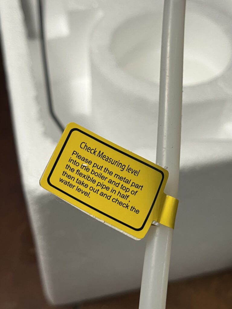
Water-Level Dipstick Tag
A separate tag associated with the water-level dipstick provides fill-level guidance and forms part of the operating information supplied with the reference unit.
Observations concerning fill level, water discharge, and possible overfill behavior are documented elsewhere in this Technical Reference and should not be treated as manufacturer-established operating limits unless supported by the supplied documentation.
Manufacturer & Distributor Documentation
Jinyun County Shengda Sewing Equipment Co., Ltd.
Shengda publishes an ST-750 Steam Boiler with principal specifications closely matching The Workshop Ledger reference unit. Published information includes the ST-750 model designation, 110 V / 220 V availability, 1600 W boiler power, 900 W iron power, and 4 L water capacity.
Shengda identifies itself as a manufacturer of electric irons, steam equipment, and related garment-finishing equipment. This documentation is useful for establishing the broader ST-750 equipment family and represents an important manufacturer lead.
It does not establish that Shengda manufactured The Workshop Ledger reference unit.
Shangrao Jiangxin Boiler Co., Ltd.
Jiangxin markets a JX-ST-750 steam boiler iron and identifies itself as a manufacturer of boilers, pressure vessels, electric steam generators, and related equipment.
This documentation provides evidence of another manufacturer-associated ST-750 configuration.
It does not establish that Jiangxin manufactured The Workshop Ledger reference unit or that the JX-ST-750 is internally identical to it.
HONKON HK-ST-750
An ST-750 steam boiler iron is marketed under the HONKON name as the HK-ST-750.
This documentation contributes evidence of another branded ST-750 configuration but does not establish common manufacture or internal equivalence with The Workshop Ledger reference unit.
TECHTONGDA / 239662
TECHTONGDA documentation for an ST-750-type steam boiler iron identifies 239662 and publishes specifications closely corresponding to The Workshop Ledger reference unit and its supplied documentation.
Published values include 4 L water capacity, 110 V electrical supply, 1600 W boiler power, 900 W iron power, 13 kg / 28.6 lb weight, and dimensions of 405 × 235 × 290 mm / 16 × 9.2 × 11.4 in.
The shared identifier and specification set establish a meaningful distribution-chain relationship. They do not establish that TECHTONGDA manufactured the reference unit.
PreAsion / 239662
A closely related steam boiler iron has also been marketed under the PreAsion name using identifier 239662.
The recurrence of the identifier under multiple retail identities supports the conclusion that 239662 originated somewhere within a shared manufacturing or distribution chain. Its exact meaning remains unresolved.
Marketplace Configurations
Current marketplace documentation identifies ST-750 equipment in configurations described as:
- Basic
- Standard
- Upgrade
- Stainless Steel
These descriptions provide evidence that multiple configurations are marketed under the ST-750 designation. The technical differences among those configurations have not yet been established.
Component Documentation
Direct examination of The Workshop Ledger reference unit has identified several components whose markings can be researched independently of documentation for the complete ST-750. External documentation has been located for several of those component families.
YIJIA YJX2-18/2P Contactor
The installed contactor is visibly marked YIJIA YJX2-18/2P.
YIJIA manufacturer documentation identifies the YJX2 family as AC contactors and documents the YJX2-18/2P as a two-pole contactor in the 18 A class.
YIJIA documentation also identifies multiple available coil-voltage configurations within the YJX2 family, including AC 24 V, AC 36 V, AC 110 V, AC 220 V, and AC 380 V.
The availability of an AC 110 V coil establishes that a 110 V configuration is manufacturer-supported. However, the coil voltage of the contactor installed in The Workshop Ledger reference unit has not yet been directly verified and should not be inferred solely from the machine’s 110 V supply voltage.
D45X / LF25-Type Pressure Control
The reference unit contains a pressure-control assembly incorporating a microswitch marked D45X.
External documentation establishes that D45X-type microswitches are used in diaphragm-operated pressure-control assemblies for steam irons, steam boilers, coffee equipment, and related pressurized steam systems.
LEFOO documentation for the LF25 Steam Pressure Switch describes a diaphragm-operated steam pressure switch using an external miniature snap-action microswitch and intended for applications including steam irons and steam-cleaning equipment. External product documentation also specifically associates LF25 and D45X designations in steam-boiler pressure-control assemblies.
The physical architecture documented in The Workshop Ledger reference unit is consistent with this type of pressurestat. The most defensible current identification is LF25-type diaphragm pressure-control assembly incorporating a D45X microswitch.
The exact manufacturer of the installed pressure-control assembly remains unresolved. The installed component should therefore not be identified as a confirmed LEFOO LF25 unless additional evidence establishes that attribution.
P/N 145230 Steam Solenoid
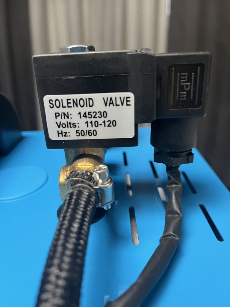
The installed steam-solenoid assembly carries the marking P/N 145230 and a visible 110–120 V electrical marking.
External component documentation identifies 145230 as a steam-iron solenoid-valve design available in configurations including brass-body construction, normally closed operation, steam service, 110 VAC coils, other AC and DC coil-voltage options, small steam-control orifices, and operating pressures suitable for small steam-ironing systems.
Current manufacturer and supplier documentation includes 145230 valves with 110 VAC coils and nominal operating pressures extending to approximately 2 bar.
This strongly supports identification of the installed component as a normally closed steam-control solenoid valve of the 145230 family.
The available evidence does not establish the original manufacturer of the valve installed in The Workshop Ledger reference unit.
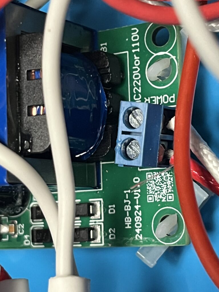
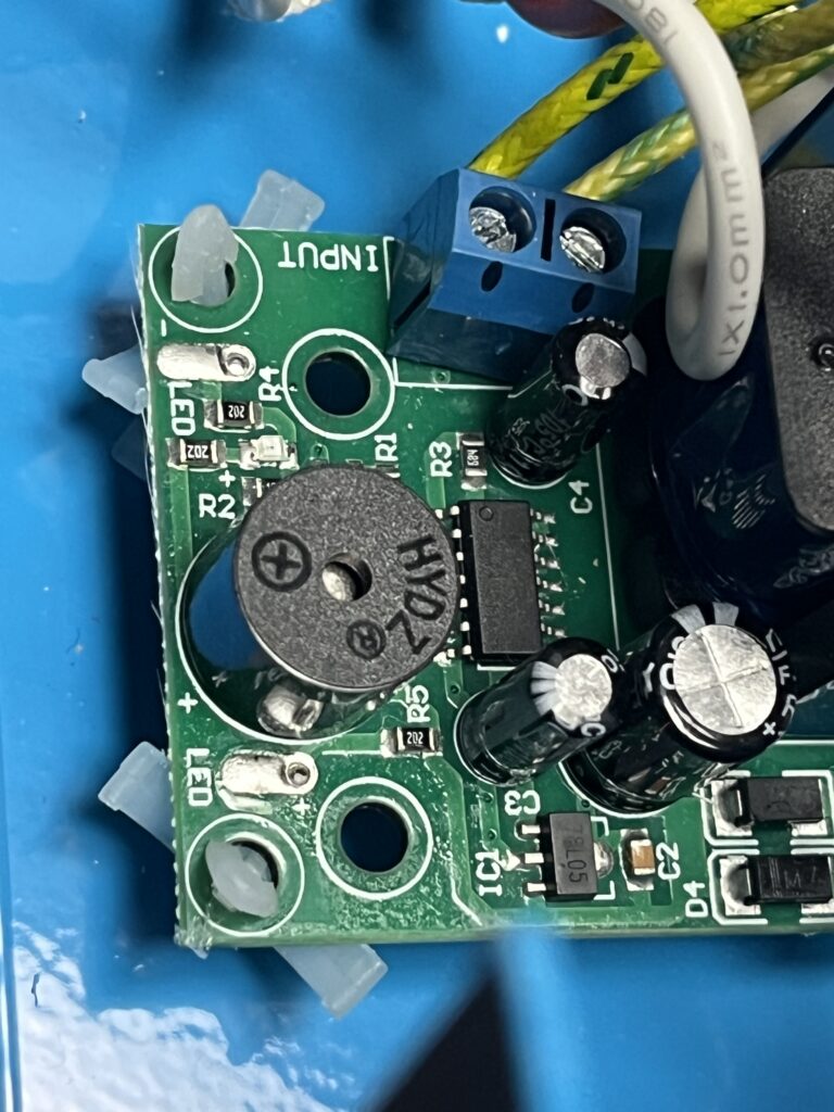
HB-BJ-1 Electronic Board
The installed electronic board is visibly marked HB-BJ-1 and 2024-09-24, and includes board markings for POWER, INPUT, and AC220V or 110V.
The board also contains two LED positions, a piezoelectric buzzer, semiconductor control components, diodes, capacitors, resistors, a substantial enclosed electromagnetic component, and separate power and input connections.
No reliable external manufacturer documentation or exact indexed match for HB-BJ-1 has yet been located.
Its physical construction and relationship to boiler-mounted sensing components are consistent with a monitoring or protection function, with water-level sensing / low-water protection presently the leading interpretation. That function remains Probable, not Confirmed.
It also remains unresolved whether the board provides warning indication only, provides an audible low-water warning, interrupts or inhibits boiler heating, or performs more than one monitoring or protection function.
The board’s exact electrical relationships remain preliminary until conductor tracing or testing establishes them.
Other Components
Additional photographed components remain unidentified or only partially identified, including:
- Boiler-mounted thermal devices
- Iron-handle microswitch marked G22 / related markings
- Pressure gauge
- Heating elements
- Other protective or control devices
Component documentation should not automatically be treated as evidence identifying the manufacturer of the complete ST-750.
Historical & Archival Documentation
Available international trade records document commercial use of the ST-750 designation by at least December 2014.
An indexed import entry describes an “INDUSTRIAL ELECTRIC STEAM IRON (3.8 LTR STEAM IRON WITH BOILER) — ITEM NO-ST-750” and identifies China as the country of origin.
The documented 3.8 L capacity differs from the 4 L capacity published for The Workshop Ledger reference unit and several current ST-750 examples. The reason for that difference and the historical machine’s relationship to current ST-750 equipment remain unresolved.
The trade record establishes documented commercial use of the ST-750 designation by at least 2014. It does not establish the original manufacturer, introduction date, continuous production, design continuity, component continuity, or a direct relationship to The Workshop Ledger reference unit.
Documentation Assessment
Available documentation is currently sufficient to establish:
- Basic published specifications of The Workshop Ledger ST-750
- Use of the ST-750 designation in international commerce by at least 2014
- Multiple manufacturer, brand, and distribution identities associated with ST-750 equipment
- Both 110 V and 220 V configurations
- Manufacturer documentation for the installed YIJIA contactor family
- External technical documentation supporting the general identification and function of the D45X / LF25-type pressure-control architecture
- External technical documentation supporting identification of the 145230 steam-solenoid family
Available documentation is not yet sufficient to establish:
- Manufacturer of The Workshop Ledger reference unit
- Complete electrical architecture
- Verified wiring diagram
- Complete pressure-control configuration
- Exact HB-BJ-1 function
- Exact thermal-protection configuration
- Complete component specifications
- Factory service procedures
- Factory replacement-parts list
Those areas presently depend upon evidence obtained through direct examination, component markings, photography, measurement, operating observations, or testing of The Workshop Ledger reference unit.
No comprehensive confirmed OEM service documentation for the reference unit has yet been located.
External Tour
The external configuration of the ST-750 combines the boiler cabinet, heated iron, steam hose, electrical connections, controls, indicators, fill access, pressure gauge, and associated fittings into a compact steam-ironing system.
This External Tour documents The Workshop Ledger reference unit as received and operated. Exterior features described here apply specifically to this reference unit and should not be assumed to be identical across all equipment carrying the ST-750 designation.
Overall Configuration
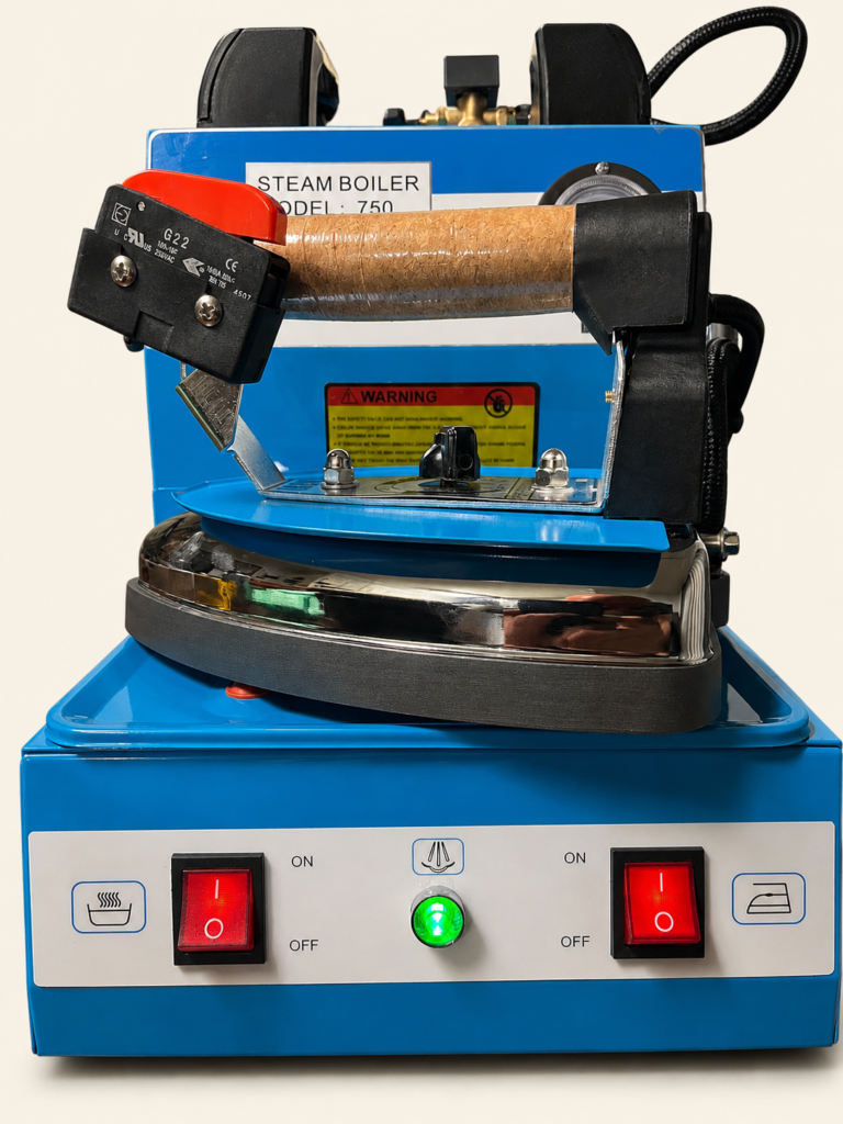
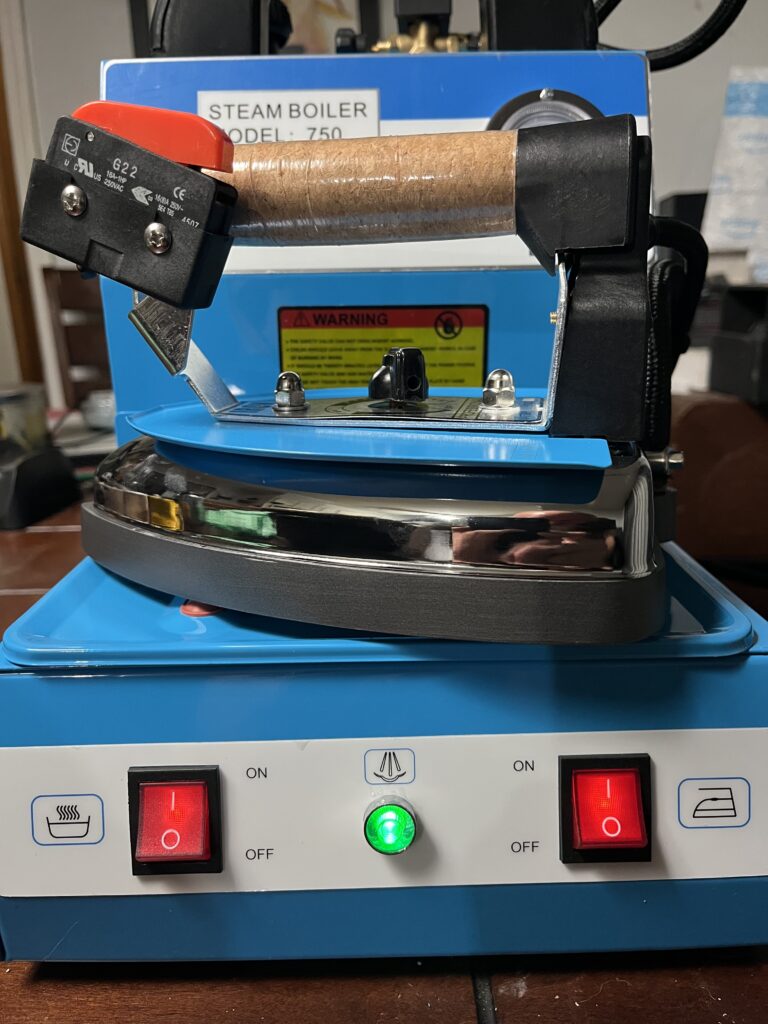
The ST-750 reference unit consists of a rectangular metal boiler cabinet with the heated iron connected by a steam hose and electrical lead. When not in use, the iron rests horizontally across the lower portion of the machine.
The cabinet contains the boiler, electrical controls, pressure-control components, steam-control system, and associated wiring and plumbing.
Externally accessible features include:
- Heated iron
- Steam hose
- Iron electrical lead
- Mains power cord
- Boiler fill opening
- Water-level dipstick
- Pressure gauge
- Front-panel controls and indicators
- Steam-adjustment control
- Cabinet access panels
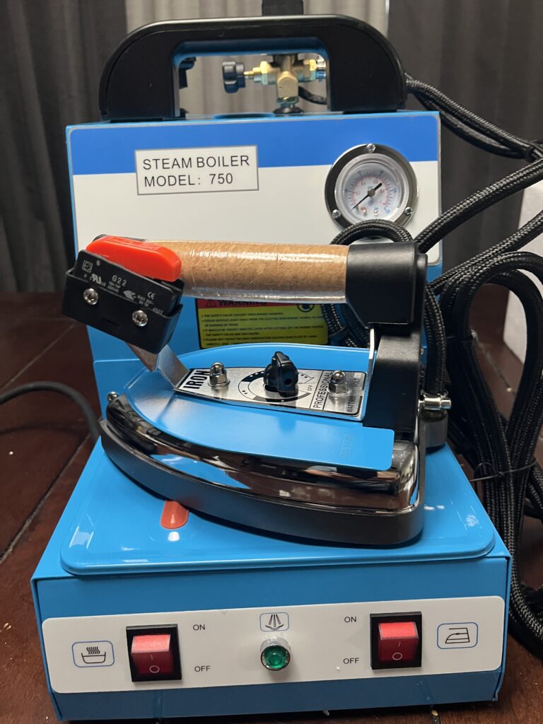
The compact arrangement allows the boiler and iron to function as a self-contained steam-ironing system suitable for localized steam application during felt-hat work.
Heated Iron
The reference unit includes an electrically heated hand iron supplied with steam from the boiler.
The iron incorporates a heated soleplate, rotary temperature control, hand-operated steam control, steam connection, and electrical connection.
The iron can provide both heat and controlled steam at the workpiece. Steam is released through the iron when the hand-operated steam control is actuated.
The iron heating circuit and steam-control circuit perform separate functions. The iron may therefore remain electrically heated independently of individual steam-release commands.
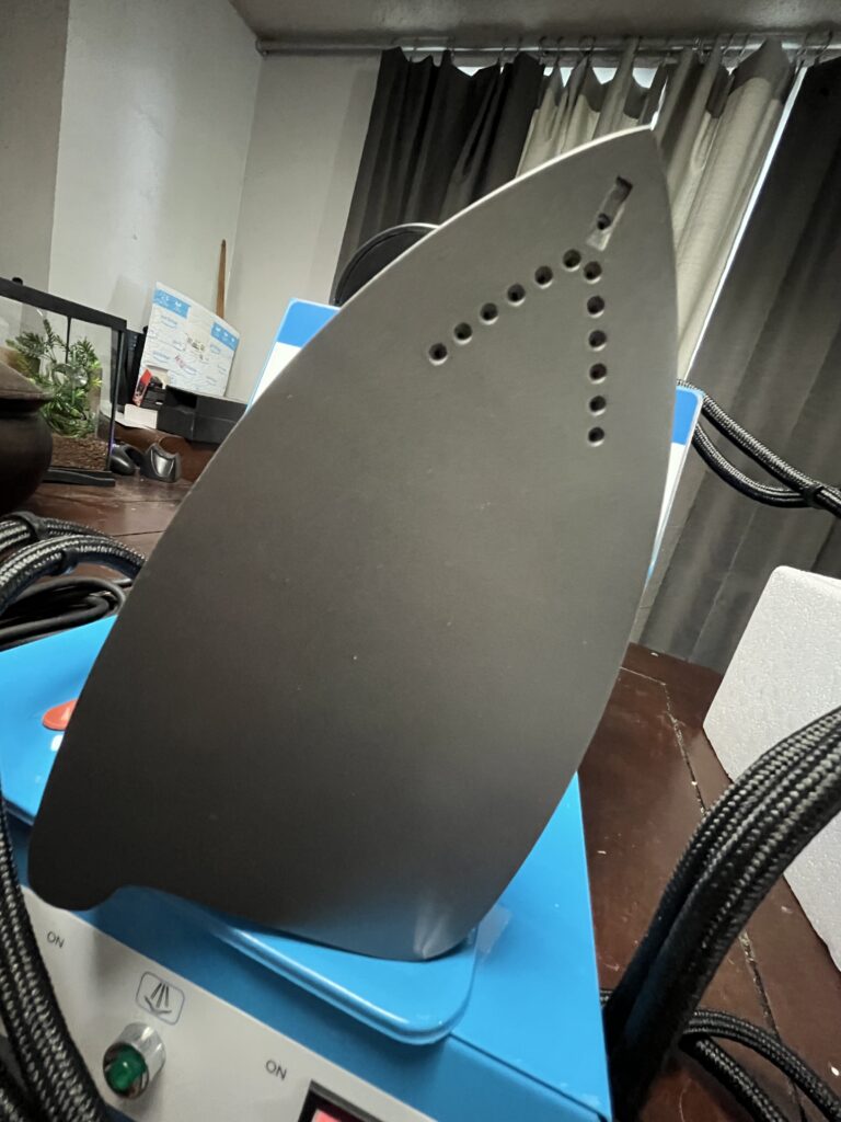
Detailed internal iron construction and component information are documented elsewhere in this Technical Reference where established.
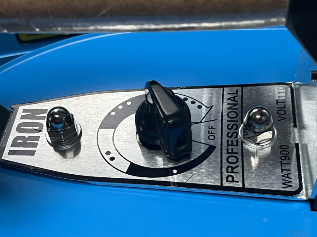
Iron Temperature Control
A rotary temperature-control dial is located on the iron. The control regulates iron heating through the iron’s internal thermostat system.
The dial provides adjustable heat appropriate to different working conditions. Exact soleplate temperatures corresponding to the control positions have not been independently measured on The Workshop Ledger reference unit.
Accordingly, dial positions should not be interpreted as verified temperature values unless supported by future direct measurement or authoritative documentation.
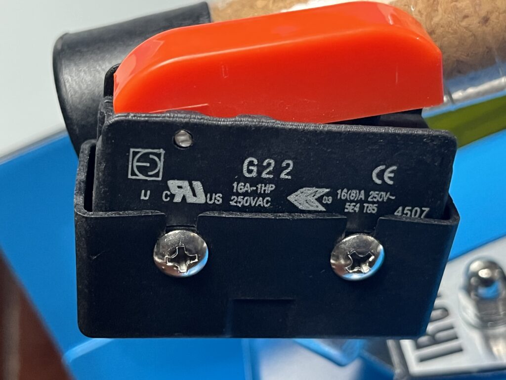
Iron Steam Control
A hand-operated steam control is incorporated into the iron handle. Actuation of this control operates an internal microswitch associated with the steam-control circuit.
During operation of The Workshop Ledger reference unit, pressing the control causes steam to be delivered through the iron.
The electrical command is associated with operation of the boiler-mounted steam solenoid valve documented elsewhere in this Technical Reference. The complete electrical path has not yet been verified terminal by terminal.
Front-Panel Controls & Indicators
The boiler cabinet includes externally accessible switches and an indicator light used during normal operation.
The left red rocker switch controls boiler heating. The right red rocker switch controls power to the heated iron. A green indicator is positioned between the two switches.
During operation of The Workshop Ledger reference unit, the green indicator has repeatedly illuminated when the installed pressure gauge reaches approximately 60 psi indicated pressure. The indicator extinguishes after sufficient pressure reduction during steam use and re-illuminates as pressure recovers to approximately the same indicated value.
This behavior is documented as an operating characteristic of The Workshop Ledger reference unit. Because the installed pressure gauge has not been independently calibrated, approximately 60 psi should be treated as an indicated pressure, not a verified absolute pressure.
The exact electrical relationship among the green indicator, pressure-control system, and other internal controls remains unresolved.
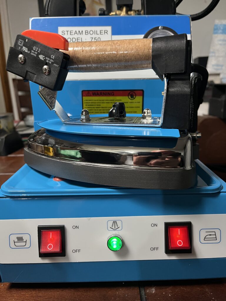
Related record: ST-750-OBS-002 — Green Pressure-Ready Indicator Behavior
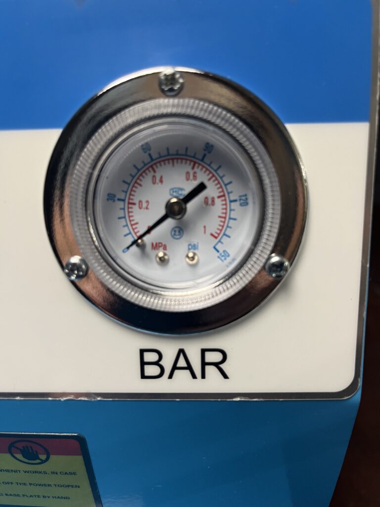
Pressure Gauge
A round analog pressure gauge is mounted externally on the boiler cabinet.
The gauge provides the operator with an indication of boiler pressure during warm-up, steam use, pressure recovery, and shutdown. It has also provided the pressure readings used to document operating behavior of The Workshop Ledger reference unit.
The installed gauge has not been independently calibrated. Pressure values recorded from this gauge are therefore identified as indicated pressure unless otherwise stated.
No gauge failure has been documented during The Workshop Ledger ownership.
Boiler Fill Opening & Water-Level Dipstick
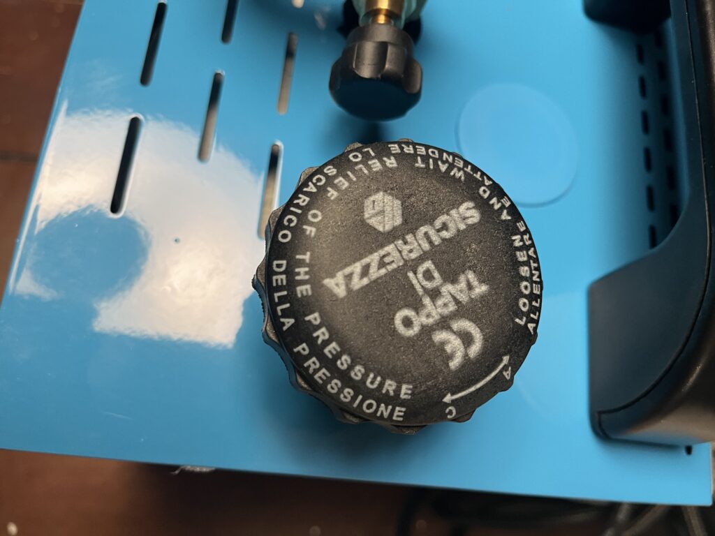
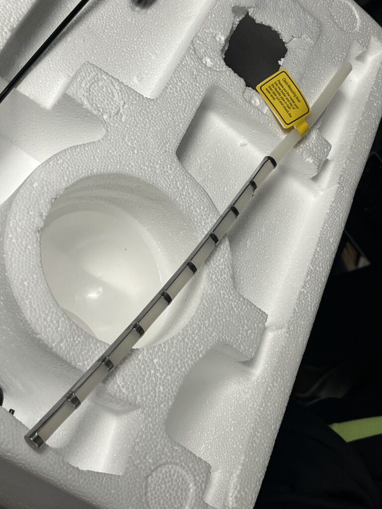
The boiler is filled through an externally accessible fill opening. A removable cap provides access to the opening, and the reference unit was supplied with a water-level dipstick and associated fill-level tag.
The published nominal boiler capacity is 4 L. This published capacity should not automatically be interpreted as the recommended normal operating fill quantity.
The first successful operation of The Workshop Ledger reference unit used approximately 2 L of distilled water. A later substantially higher fill was associated with significant liquid-water carryover and sputtering from the iron.
The exact manufacturer-recommended operating fill range has not been established.
Related record: ST-750-OBS-003 — High Fill-Level Water Carryover
Steam Adjustment
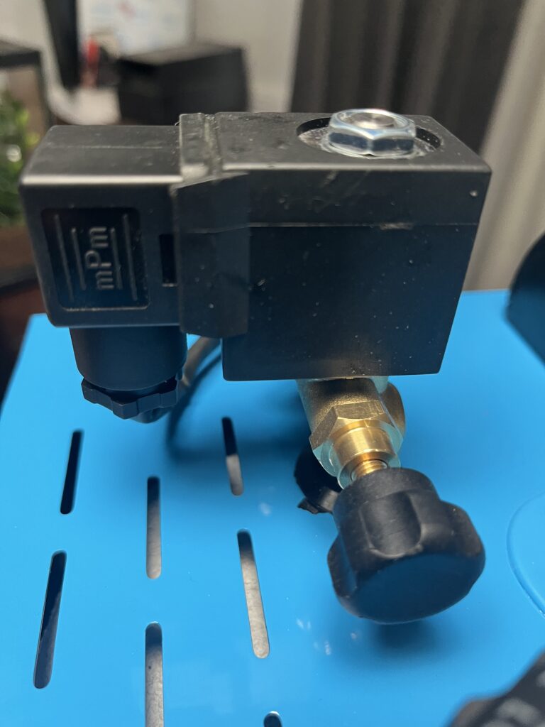
An externally accessible steam-adjustment control is provided on the machine.
The control affects steam delivery available through the iron. The practical relationship between control position and steam output has not been quantitatively characterized.
The control is therefore documented according to its observed operating function rather than assigned unsupported numerical flow values.
Steam Hose
A flexible steam hose connects the boiler system to the iron. The hose carries pressurized steam from the boiler-mounted steam-control system to the iron.
The Workshop Ledger measurement of the hose exterior should be interpreted only according to the documented measurement points and should not automatically be treated as the hose’s nominal internal diameter or fitting specification.
During operation, the hose and its connections are exposed to heat, steam, pressure, flexing, and repeated handling.
No steam-hose failure has been documented during The Workshop Ledger ownership. Detailed fitting and replacement specifications have not yet been established.
External Electrical Connections
The reference unit supplies electrical power to both the boiler system and heated iron.
Externally visible electrical components include the mains power cord and plug, iron electrical lead, front-panel switches, and associated strain-relief and cable-routing points.
Electrical ratings, protective grounding, safety considerations, and internal circuit construction are documented elsewhere in this Technical Reference.
Exterior Labels & Markings
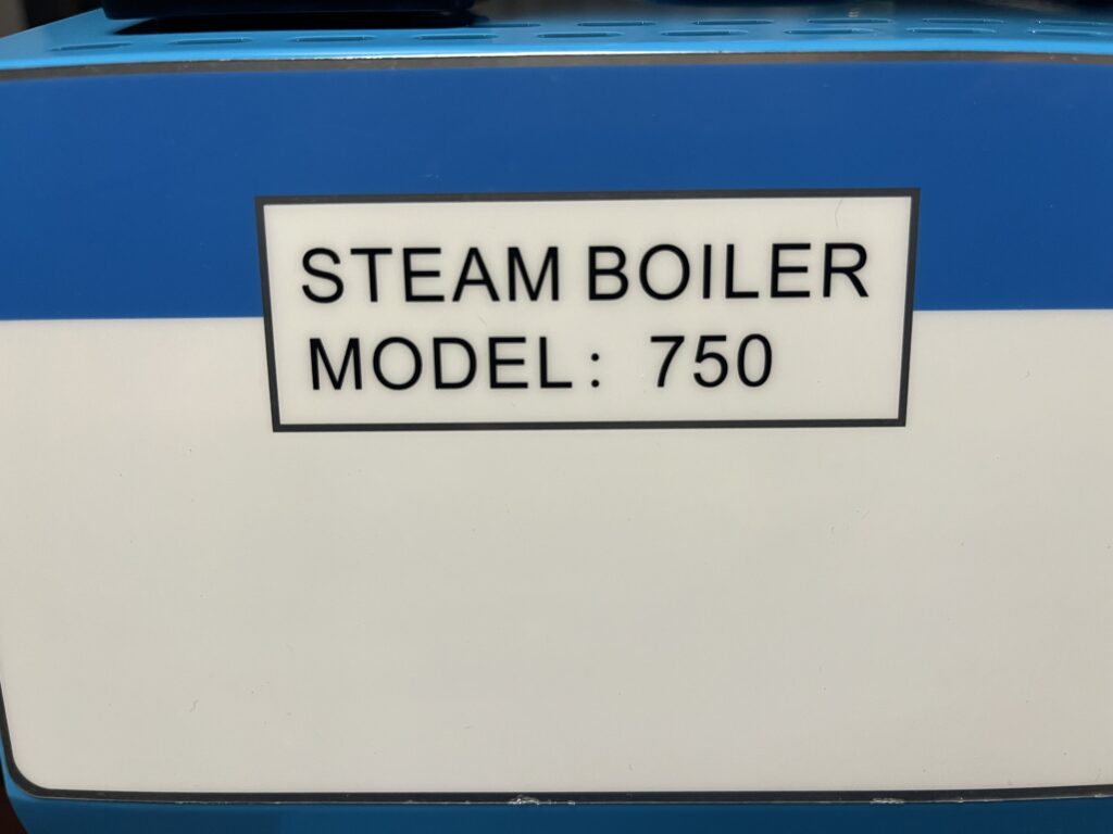
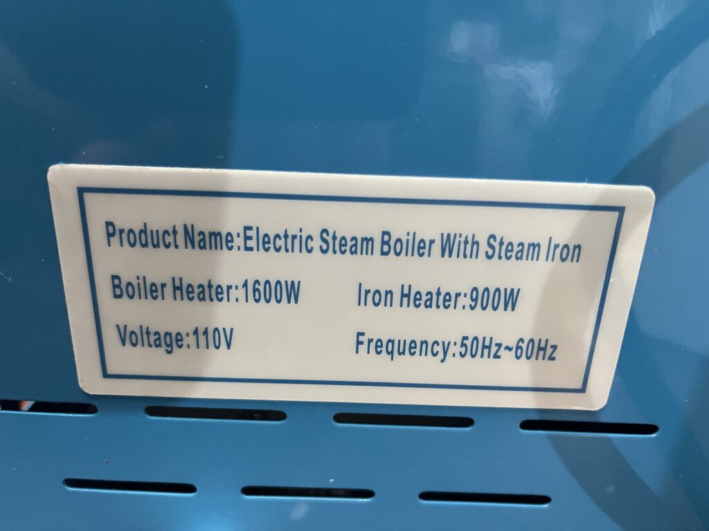
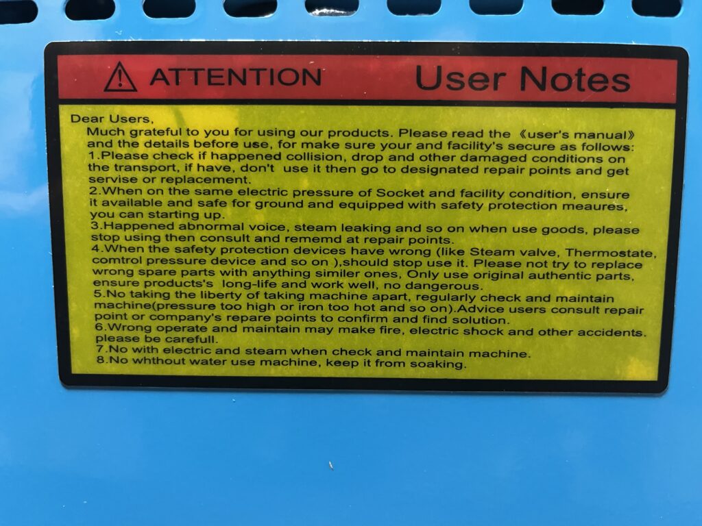
Exterior labels, markings, control symbols, model identification, and other identifying information present on the reference unit provide evidence concerning model identity, electrical ratings, control functions, safety information, manufacturing origin, production changes, and variant identification.
No exterior manufacturer marking presently documented on The Workshop Ledger reference unit conclusively identifies the physical manufacturer.
External Condition of the Reference Unit
The Workshop Ledger reference unit was acquired new in 2026 and arrived without significant exterior damage affecting operation.
Initial inspection and operation established that the major externally accessible systems were functional, including boiler heating, pressure indication, front-panel controls, heated iron, iron temperature control, hand-operated steam control, steam delivery, and steam-hose connections.
No external steam or water leakage was observed during the initial successful operating session.
The first deliberate cold-start test established a warm-up time of 19 min 57.92 sec, measured from a cold starting condition to the first illumination of the green pressure-ready indicator.
Related test: ST-750-TST-001 — Cold-Start Warm-Up Time
Subsequent operation documented two significant conditions: high-fill water carryover and repeated branch-circuit breaker trips on a shared 15 A circuit.
During the high-fill event, a substantially greater water quantity than used during the initial successful test was associated with liquid-water carryover and sputtering from the iron. The event does not presently establish a component failure and instead demonstrates the importance of establishing an appropriate operating fill level.
During separate operation, the machine repeatedly tripped the breaker protecting a shared 15 A branch circuit. The event does not presently establish an electrical fault within the ST-750; the circuit was also supplying other loads, and the machine’s published boiler and iron ratings represent substantial combined electrical demand.
Related observation: ST-750-OBS-003 — High Fill-Level Water Carryover
Related observation: ST-750-OBS-004 — Shared 15 A Branch-Circuit Breaker Trips
The reference unit remains the primary physical basis for The Workshop Ledger ST-750 Technical Reference. Future changes in condition, operating behavior, measurements, or configuration will be documented against this baseline.
Internal Tour
Removal of the ST-750 cabinet provides access to the boiler, steam-control system, pressure-control components, electrical controls, protective devices, wiring, and associated plumbing.
This Internal Tour documents the physical arrangement of The Workshop Ledger reference unit as observed during direct examination.
Detailed specifications, external component research, replacement information, and individual component records are documented separately under Component Reference. Detailed circuit interpretation is documented under Wiring & System Diagrams.
The internal construction described here applies specifically to The Workshop Ledger reference unit and should not be assumed to be identical across all machines carrying the ST-750 designation.
Internal Overview
The boiler occupies the majority of the cabinet interior. Electrical, pressure-control, steam-control, and protective components are arranged around the boiler and attached to the chassis or associated mounting points.
Major systems and components visible with the cabinet removed include:
- Pressure boiler
- Boiler heating system and associated conductors
- Pressure-control assembly
- YIJIA YJX2-18/2P contactor
- HB-BJ-1 electronic board
- P/N 145230 steam-solenoid assembly
- Steam plumbing and fittings
- Pressure-gauge connection
- Boiler-mounted thermal devices
- Insulated electrical penetrations associated with the boiler
- Barrier terminal strip
- Protective grounding
- Wiring harnesses
- External control connections
The internal arrangement is compact, with steam plumbing and mains-voltage electrical components located within the same enclosure.
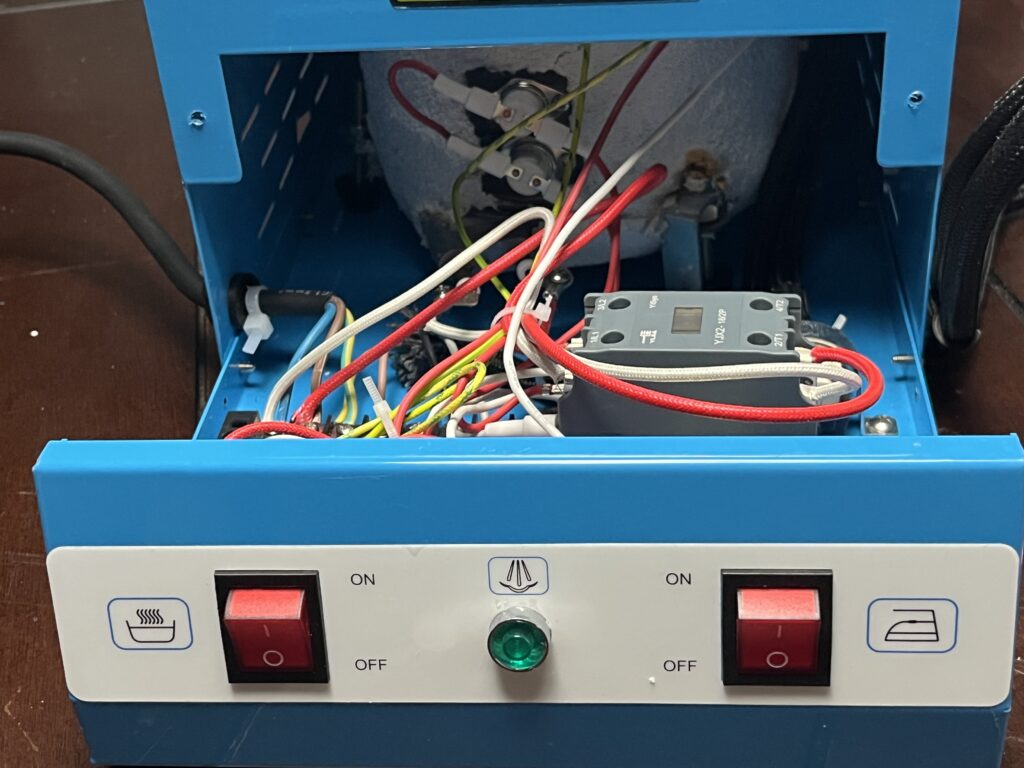
Major Internal Components
Pressure Boiler
The pressure boiler occupies much of the rear portion of the cabinet and serves as the machine’s water reservoir and steam-generation vessel.
The heating system, steam outlet, pressure-control system, pressure indication, thermal devices, filling system, and other fittings are physically associated with the boiler.
The supplied documentation specifies a nominal water capacity of 4 L. No manufacturer or pressure-vessel identification has been established from the available markings or photographs.
The boiler’s exact material, wall thickness, internal dimensions, working-pressure rating, and pressure-test rating remain unresolved.
Boiler Heating System
The boiler incorporates an electric heating system used to heat the contained water and generate steam.
Manufacturer-supplied documentation specifies the boiler heating load as 1600 W.
High-temperature insulated conductors associated with the boiler heating circuit are visible within the cabinet. The heating circuit is switched through the machine’s electrical-control system rather than relying solely on the front-panel boiler switch to carry the heating load directly.
The exact construction, resistance, and physical configuration of the heating element have not yet been independently established.
Boiler-Mounted Thermal Devices
Two round thermal devices are mounted directly against the exterior of the boiler on The Workshop Ledger reference unit.
Each device has two electrical terminals connected by insulated conductors. Their direct physical contact with the boiler indicates that they respond to boiler temperature, but their individual control or protective functions have not yet been conclusively established.
No legible manufacturer, model, temperature rating, or switching specification has yet been documented from the installed devices. They should therefore not be assigned specific thermostat, thermal-limit, or safety-cutoff functions without additional evidence.
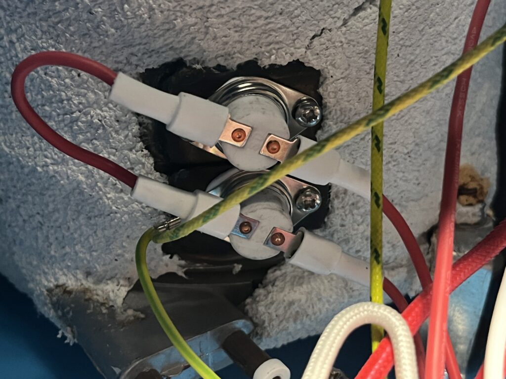
Pressure-Control Assembly
The ST-750 reference unit uses a mechanical diaphragm-type pressure-control assembly connected to the boiler-pressure system.
Pressure acting on the mechanical assembly operates an external snap-action microswitch. The installed microswitch is visibly marked D45X and carries electrical ratings including 16(4)A 250VAC, 15A 125–250VAC, and 1/2HP 125–250VAC.
The overall construction closely resembles the architecture used by LF25-type diaphragm pressurestats. However, no manufacturer or model marking has been documented on the complete installed pressure-control assembly. It should therefore not be identified as a confirmed LF25 or assigned to a particular manufacturer.
Observed operation establishes that boiler heating cycles as pressure rises and falls during use. The exact pressure-control switching thresholds have not yet been independently measured.
The precise electrical relationship among the pressure-control assembly, contactor, green pressure-ready indicator, and other control components remains subject to further electrical tracing and controlled testing.
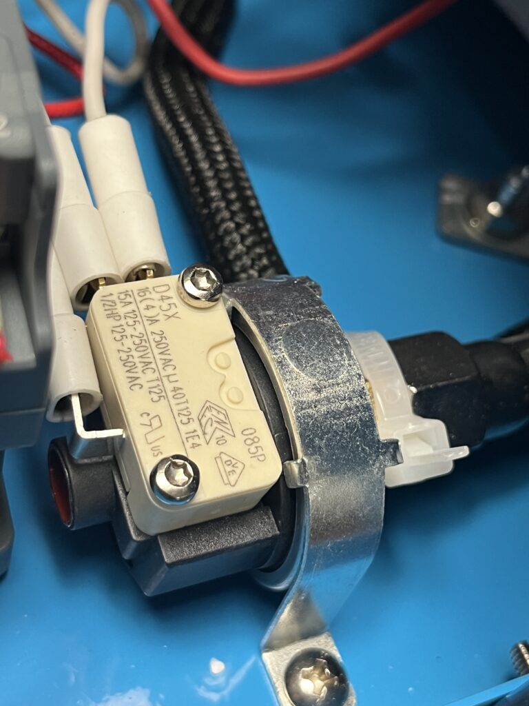
YJX2-18/2P Contactor
A YJX2-18/2P two-pole contactor is installed within The Workshop Ledger reference unit. The component carries YiSys and YIJIA markings on its face.
The contactor is positioned in the lower portion of the cabinet and forms part of the boiler-heating control system. Its use allows the higher-current boiler-heating load to be switched through the contactor rather than directly through the pressure-control microswitch.
The installed contactor carries a 110 V AC coil. Additional terminal and load ratings are documented in the Component Reference.
The presence of the contactor is significant to understanding the ST-750 control architecture: the pressure-control system can provide a control signal while the contactor performs the higher-current switching required by the boiler heater.
The complete circuit path has not yet been verified terminal by terminal. Accordingly, the contactor’s documented role is based on its installed configuration, component type, and presently established circuit relationships rather than a completed wiring trace.
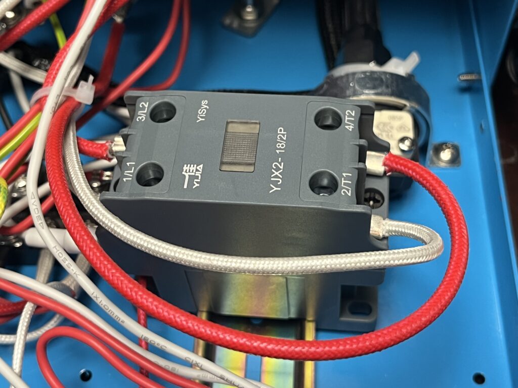
HB-BJ-1 Electronic Board
An electronic control board marked HB-BJ-1 is installed within The Workshop Ledger reference unit.
The board is additionally marked 240924-U10. Visible components include a transformer, terminal connections, semiconductor components, electrolytic capacitors, an integrated circuit, indicator LEDs, and an onboard piezoelectric buzzer.
Printed markings on the board identify connection points including INPUT and LED1. Additional component-designation markings are visible on the printed circuit board.
The board forms part of the machine’s electrical-control system, but its complete function and relationship to the boiler heating, pressure-control, indicator, and protection circuits have not yet been established through terminal-by-terminal circuit tracing.
No authoritative schematic or manufacturer documentation for the HB-BJ-1 board has yet been located. Specific control functions should therefore not be assigned to the board until supported by circuit tracing, component documentation, or other authoritative evidence.
Internal Wiring and Connections
The internal electrical system of The Workshop Ledger reference unit uses multiple wire types, terminal connections, insulated connectors, and protective sleeving to interconnect the boiler heating system, controls, indicators, contactor, electronic board, iron, and other electrical components.
Visible wiring includes conductors with heat-resistant braided insulation in areas associated with higher-temperature components, conventional insulated conductors elsewhere within the cabinet, and green/yellow protective-earth conductors.
Individual connections include insulated push-on terminals, screw terminals, and other mechanically secured electrical connections. Cable ties and routing through the cabinet are used to organize and restrain portions of the wiring.
The internal wiring has been photographically documented, but a complete terminal-by-terminal circuit trace has not yet been performed. Wire color, physical proximity, or apparent routing should therefore not by themselves be interpreted as proof of electrical function.
A verified wiring diagram for The Workshop Ledger reference unit has not yet been produced. Development of such a diagram will require systematic continuity testing and circuit tracing with the machine disconnected from electrical power.
Protective Grounding
Protective-earth wiring is present within The Workshop Ledger reference unit and is identifiable by green/yellow insulated conductors.
The protective-grounding system is intended to provide an electrical connection between exposed conductive portions of the machine and the grounding conductor of the electrical supply.
Green/yellow conductors are visibly routed within the cabinet, including wiring in the vicinity of the boiler assembly and metal chassis.
The complete protective-earth path has not yet been verified through continuity testing. Accordingly, the presence and routing of the visible grounding conductors are documented here without making unsupported claims regarding measured grounding resistance or continuity to every exposed metal component.
Internal Steam & Pressure Pathways
Boiler-to-Iron Steam Path
Water heated within the boiler generates steam that passes from the boiler through the machine’s steam-control plumbing toward the iron.
The documented pathway includes the boiler, steam outlet plumbing, manual steam-adjustment system, electrically actuated P/N 145230 steam-solenoid valve, flexible steam hose, and heated iron.
Operation of the hand control on the iron actuates its internal microswitch. During normal operation, this command results in opening of the steam-control path and delivery of steam through the iron.
The overall boiler-to-iron steam pathway is confirmed at the functional level. The internal flow characteristics and quantitative effect of the manual steam-adjustment control have not yet been established.
Pressure-Control Path
Boiler pressure is mechanically communicated to the diaphragm-type pressure-control assembly.
Pressure-induced movement within the assembly actuates the externally mounted D45X microswitch, allowing boiler pressure to participate in control of the heating system.
This mechanical relationship is directly documented on The Workshop Ledger reference unit. The exact pressure-control cut-in and cut-out values have not yet been independently measured.
Pressure-Gauge Path
The external pressure gauge is connected to the boiler-pressure system through associated pressure plumbing and fittings.
This connection allows the gauge to indicate system pressure during warm-up, steam use, pressure recovery, and shutdown.
The pressure pathway is confirmed, but the installed gauge has not been independently calibrated. Pressure readings documented throughout this Technical Reference are therefore identified as indicated pressure unless otherwise stated.
Internal Construction Details
Cabinet & Chassis Arrangement
The removable painted-metal cabinet encloses the pressure vessel, electrical system, and steam plumbing while providing mounting locations for the machine’s external controls and fittings.
The boiler and principal control components are supported by the internal chassis rather than relying upon the removable cabinet cover for primary structural support.
Removal of the cabinet exposes the major internal systems for inspection and service while leaving the boiler and principal components mounted in their operating relationships.
Electrical & Steam-System Proximity
Steam plumbing, high-temperature boiler components, and mains-voltage electrical components occupy the same compact enclosure.
Heat-resistant insulation and sleeving are used on conductors and other components in areas exposed to elevated temperatures.
Because electrical and steam systems operate in close physical proximity, the condition and routing of wiring, insulation, fittings, and steam connections are particularly relevant during inspection and service.
High-Temperature Wiring
Several conductors associated with the boiler use heat-resistant insulation or sleeving appropriate to their location near the pressure vessel and heating system.
Visible conductor colors, insulation types, and routing document the construction of The Workshop Ledger reference unit and should not be assumed to represent a universal ST-750 wiring standard.
Condition of this insulation is significant because deterioration near heated components can expose conductors or compromise electrical isolation.
Internal Condition
The internal components examined appear substantially complete, and the machine has successfully generated pressure, heated the iron, and delivered steam during operation.
No internal steam or water leak was documented during the initial operating session using approximately 2 L of water.
Several internal condition findings are relevant to continued inspection, operation, and service.
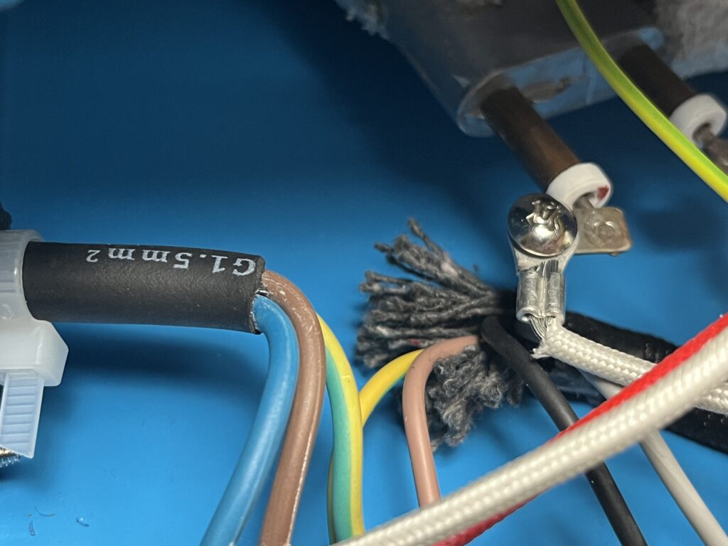
Frayed Heat-Resistant Textile / Sleeving
A gray braided or fibrous material visible near the boiler and electrical area shows localized fraying or deterioration.
Its exact material and function have not been established. It may represent heat-resistant sleeving, insulation, packing, or another temperature-resistant textile component.
Because its composition and function remain unresolved, the material is documented as a condition finding rather than characterized as a failed component.
General Internal Condition
Aside from the specifically documented frayed fibrous material, no obvious burned wiring, melted insulation, severely discolored electrical terminals, or visibly failed internal component was identified during the initial internal examination.
The boiler exterior, electrical components, steam-control components, wiring, and connections show the condition of a newly acquired reference unit that has undergone limited operation and inspection.
Visual inspection alone cannot establish the electrical or mechanical condition of every component. These observations therefore document visible condition only and should not be interpreted as electrical safety testing, pressure-vessel inspection, or certification of the machine.
Reference-Unit Construction Record
The internal photographs in this Technical Reference preserve the construction of The Workshop Ledger reference unit as received in 2026.
Component selection, wiring arrangement, fittings, control devices, and other construction details may differ among machines sold under the ST-750 designation. These photographs should therefore be treated as documentation of this specific reference unit rather than as proof of a universal ST-750 configuration.
Future examination of additional ST-750 units may allow construction differences, production revisions, and component substitutions to be identified and documented.
Unresolved Internal Questions
Internal examination has substantially improved documentation of the ST-750 reference unit, but several aspects of its construction remain unresolved, including:
- Complete terminal-by-terminal electrical circuit routing
- Exact function of the HB-BJ-1 electronic board
- Boiler pressure-control cut-in and cut-out thresholds
- Relationship between the pressure-control assembly, D45X microswitch, contactor, electronic board, and green indicator
- Identification and function of the frayed gray fibrous material
- Positive identification of steam and pressure fitting thread types
- Protective-earth continuity throughout the machine
- Whether internal construction differs among other ST-750 examples
These unresolved questions are retained deliberately rather than filled with assumptions. As additional evidence becomes available through testing, component research, manufacturer documentation, or examination of other ST-750 units, the applicable portions of this Technical Reference will be revised.
Component Reference
This section documents significant components identified within The Workshop Ledger ST-750 reference unit.
Component identification is based on direct examination, visible markings, photographs, external component documentation, physical relationships, and observed system behavior.
Identification of a component family does not establish every electrical, mechanical, pressure, or temperature specification of the component installed in the reference unit.
Likewise, visual similarity to a commercially available component is not treated as conclusive identification.
Replacement compatibility is addressed separately in the Parts & Replacement Guide.
Component Index
The following index summarizes the current identification status of significant components documented in The Workshop Ledger reference unit.
Main Contactor
Identifier / Marking: YJX2-18/2P — YiSys / YIJIA markings
Function: High-current electrical switching associated with boiler heating and control
Identification Status: Confirmed
Pressure-Control Microswitch
Identifier / Marking: D45X
Function: Electrically switches in response to mechanical movement of the pressure-control assembly
Identification Status: Confirmed
Pressure-Control Assembly
Identifier / Marking: LF25-type family match; D45X marking belongs to attached microswitch
Function: Responds mechanically to boiler pressure and actuates the D45X microswitch
Identification Status: Probable
Steam Solenoid Valve
Identifier / Marking: P/N 145230
Function: Electrically controls steam flow toward the iron
Identification Status: Partially Identified
HB-BJ-1 Electronic Board
Identifier / Marking: HB-BJ-1 / 240924-U10
Function: Electronic control or monitoring function within the boiler-control system
Identification Status: Partially Identified
Pressure Gauge
Identifier / Marking: No complete identification established
Function: Indicates boiler-system pressure
Identification Status: Function Confirmed / Identity Unresolved
Boiler Heating System
Identifier / Marking: No complete identification established
Function: Heats boiler water to generate steam
Identification Status: Function Confirmed / Identity Unresolved
Iron Heating System
Identifier / Marking: No complete identification established
Function: Heats the iron soleplate
Identification Status: Function Confirmed / Identity Unresolved
Iron Thermostat
Identifier / Marking: No complete identification established
Function: Controls iron heating according to the temperature setting
Identification Status: Function Confirmed / Identity Unresolved
Iron Steam-Control Microswitch
Identifier / Marking: G22 / related visible markings
Function: Provides the electrical input associated with the hand-operated steam command
Identification Status: Partially Identified
Boiler-Mounted Thermal Devices
Identifier / Marking: Markings unresolved
Function: Probable temperature-responsive protection or control
Identification Status: Unresolved
Boiler Electrical / Sensing Penetrations
Identifier / Marking: No complete identification established
Function: Probable sensing or control input associated with the boiler
Identification Status: Unresolved
Barrier Terminal Strip
Identifier / Marking: No complete identification established
Function: Internal electrical connection and distribution
Identification Status: Function Confirmed / Identity Unresolved
The index summarizes the current identification status of components documented in the reference unit. Detailed evidence, known specifications, functional relationships, and identification limitations are documented below.
Identified & Partially Identified Components
Main Contactor — YJX2-18/2P
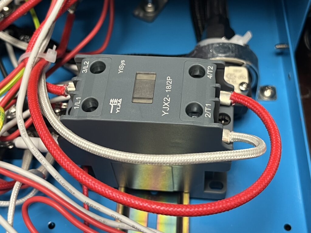
A YJX2-18/2P two-pole electrical contactor is installed within the electrical/control area of The Workshop Ledger reference unit. The installed component carries YiSys and YIJIA markings on its face.
Visible terminal markings include 1/L1, 2/T1, 3/L2, and 4/T2. These markings identify two switched power paths through the contactor.
Its installed location and wiring establish that the contactor is associated with high-current switching within the boiler-heating control system. This allows the boiler-heating load to be switched through a dedicated contactor rather than requiring the full heater current to pass directly through smaller control devices.
The complete control circuit has not yet been verified terminal by terminal.
Identification & Specifications
Component Type: Two-pole electrical contactor
Markings: YiSys / YIJIA / YJX2-18/2P
Power Terminals: 1/L1, 2/T1, 3/L2, 4/T2
Location: Internal electrical/control area adjacent to the boiler
Function: High-current switching associated with boiler heating and control
Identification Status: Confirmed
External documentation for the YJX2-18/2P family indicates that multiple coil-voltage configurations exist. The model designation alone therefore should not be used to determine the coil voltage or select a replacement contactor.
Replacement selection requires verification of the installed coil voltage, contact configuration, current capacity, mounting arrangement, and terminal configuration. Additional replacement considerations are documented in the Parts & Replacement Guide.
Pressure-Control Microswitch — D45X
The pressure-control assembly on The Workshop Ledger reference unit incorporates an externally mounted snap-action microswitch visibly marked D45X.
The switch is mechanically actuated by movement of the pressure-responsive mechanism. Boiler pressure acts upon the mechanical pressure-control assembly, and movement of that assembly actuates the D45X microswitch, allowing the pressure-control system to influence the machine’s electrical-control circuit.
The D45X marking belongs specifically to the microswitch and should not be interpreted as the model designation of the complete pressure-control assembly.
The complete electrical path controlled by the D45X microswitch has not yet been traced terminal by terminal.
Identification & Specifications
Component Type: Mechanically actuated snap-action microswitch
Marking: D45X
Manufacturer: Unresolved
Location: Mounted externally on the boiler pressure-control assembly
Function: Electrical switching in response to mechanical movement of the pressure-control assembly
Identification Status: Confirmed as the installed microswitch; exact manufacturer unresolved
Visible Electrical Ratings:
16(4)A 250VAC
15A 125–250VAC
1/2HP 125–250VAC
These ratings are transcribed from the installed component and document the markings present on The Workshop Ledger reference unit. They do not by themselves establish the switch’s contact configuration, suitability for a particular replacement application, or the electrical load actually carried by the switch in the ST-750.
The D45X marking alone is insufficient to identify a complete replacement pressurestat. Replacement of either the microswitch or complete pressure-control assembly requires additional verification of mechanical compatibility, electrical configuration, operating pressure range, and switching behavior.
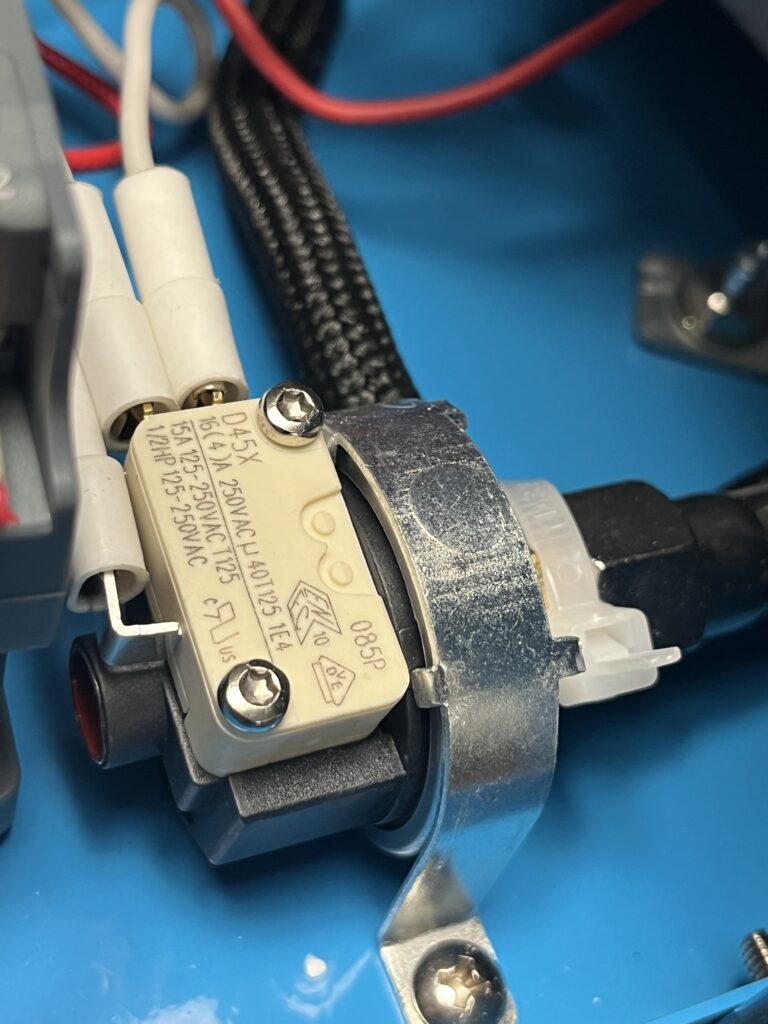
Pressure-Control Assembly — LF25-Type
The installed pressure-control assembly consists of a pressure-responsive mechanical body connected to the boiler-pressure system and the externally mounted D45X microswitch documented above.
Boiler pressure acts mechanically upon the assembly. Pressure-induced movement within the mechanism actuates the D45X microswitch, allowing changes in boiler pressure to influence the machine’s electrical-control system.
The construction of the installed assembly closely resembles documented LF25-type diaphragm pressure-control assemblies. Available evidence therefore supports an LF25-type family identification, but no marking presently documented on the complete installed assembly establishes its exact manufacturer or model.
Accordingly, LF25-type is a probable family identification rather than a confirmed model identification. The installed assembly should not be represented as a confirmed LF25 or attributed to a particular manufacturer without additional evidence.
Observed boiler operation confirms pressure-dependent cycling, but the actual cut-in pressure, cut-out pressure, and differential of the installed pressure-control assembly have not yet been independently measured. The approximately 60 psi indicated behavior of the green pressure-ready indicator should not automatically be interpreted as either pressure-control switching threshold.
Identification & Specifications
Component Type: Mechanical diaphragm pressure-control assembly / pressurestat-type control
Family Identification: LF25-type
Exact Manufacturer: Unresolved
Exact Model: Unresolved
Pressure-Switching Element: External D45X microswitch
Installed Cut-In Pressure: Not independently measured
Installed Cut-Out Pressure: Not independently measured
Differential: Unresolved
Location: Adjacent to the boiler and connected to the boiler-pressure system
Function: Responds mechanically to boiler pressure and actuates the D45X microswitch
Identification Status: Probable
The exact electrical relationship among the pressure-control assembly, contactor, green pressure-ready indicator, HB-BJ-1 electronic board, thermal devices, and other control components remains only partially documented.
A replacement pressure-control assembly should not be selected solely because it resembles an LF25-type device. Pressure range, differential, electrical configuration, pressure connection, mounting dimensions, actuation behavior, and compatibility with the ST-750 control system would all require verification.
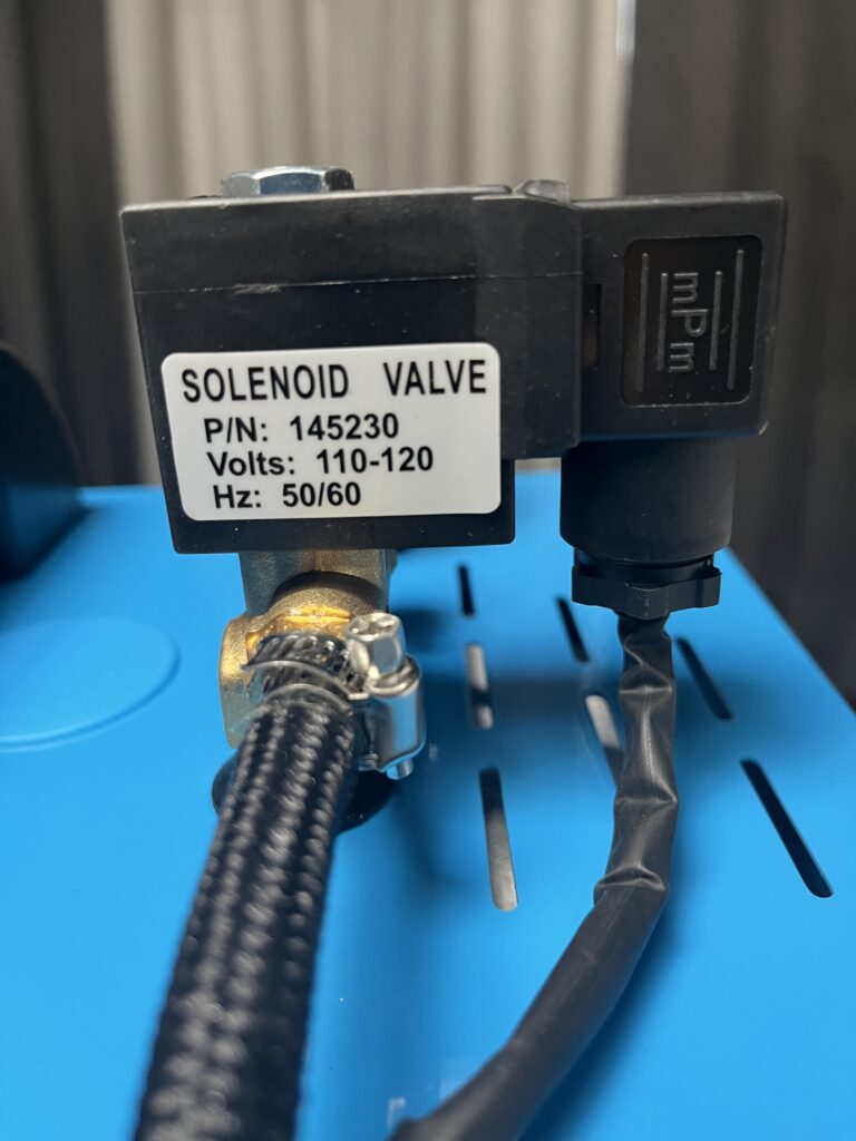
Steam Solenoid Valve — P/N 145230
An electrically actuated steam-control valve marked P/N 145230 is installed in the steam-delivery path between the boiler system and the iron.
During normal operation, pressing the hand-operated steam control on the iron results in steam delivery through the iron. The installed solenoid valve is electrically and mechanically associated with this function, opening the steam path in response to the steam-control command.
The installed solenoid is visibly marked P/N 145230, 110–120 V, and 50/60 Hz. These markings provide direct evidence of the electrical rating of the installed coil.
External documentation for 145230-family steam valves supports their use as electrically actuated valves in steam-ironing equipment. However, the available evidence does not conclusively establish the manufacturer of the valve installed in The Workshop Ledger reference unit.
The complete electrical path between the iron steam-control microswitch and solenoid coil has not yet been traced terminal by terminal.
Identification & Specifications
Component Type: Electrically actuated steam solenoid valve
Part Marking: P/N 145230
Installed Voltage Marking: 110–120 V
Frequency Marking: 50/60 Hz
Manufacturer: Unresolved
Location: Steam-delivery path between boiler system and iron
Function: Electrically controls steam flow toward the iron
Port / Thread Specification: Unresolved
Pressure Rating: Not independently established for the installed valve
Temperature Rating: Unresolved
Valve Configuration: Not independently established
Identification Status: Partially Identified
The P/N 145230 marking and visible electrical ratings provide substantially more information than visual similarity alone, but they are still insufficient to establish a verified replacement valve.
Replacement compatibility would require confirmation of valve configuration, pressure and temperature capability, steam compatibility, port dimensions and thread type, mounting arrangement, coil characteristics, and physical fit. Additional replacement considerations are documented in the Parts & Replacement Guide.
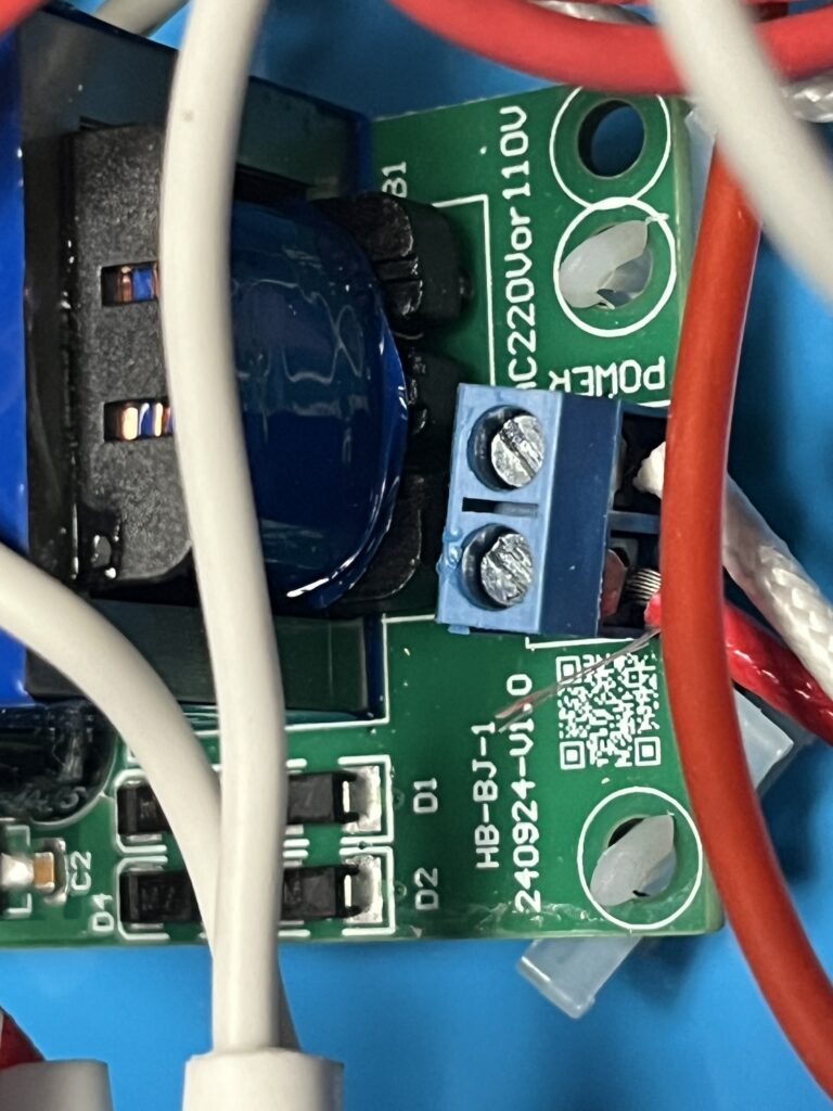
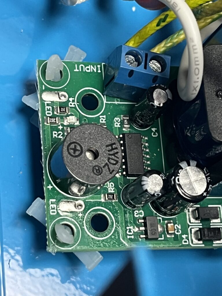
HB-BJ-1 Electronic Board
An electronic control board marked HB-BJ-1 is installed within the electrical/control area of The Workshop Ledger reference unit.
Direct examination documents a transformer, terminal connections, semiconductor components, electrolytic capacitors, an integrated circuit, indicator LEDs, and an onboard piezoelectric buzzer. Printed markings on the board include HB-BJ-1, 240924-U10, INPUT, and LED1.
The board is electrically integrated into the machine’s boiler-control system, but its exact inputs, outputs, and control authority have not yet been established through terminal-by-terminal circuit tracing.
Its physical relationship to boiler sensing components supports a possible role involving water-level monitoring, low-water protection, alarm indication, or another boiler-monitoring function. That interpretation remains Probable, not Confirmed.
The presence of the onboard buzzer and indicator LEDs establishes that the board has audible and visual indication capability. It does not, by itself, establish what condition causes those devices to operate.
No authoritative manufacturer documentation, schematic, or verified replacement specification for the HB-BJ-1 board has yet been located.
Identification & Specifications
Component Type: Electronic control / monitoring board
Board Marking: HB-BJ-1
Additional Marking: 240924-U10
Visible Connection Marking: INPUT
Visible Indicator Marking: LED1
Visible Indicators: LEDs
Audible Device: Piezoelectric buzzer
Manufacturer: Unresolved
Exact Function: Unresolved
Location: Internal electrical/control area
Identification Status: Partially Identified
The 240924-U10 marking is preserved as it appears on the physical board. Although part of the marking could represent a production or date code, its meaning has not been independently established and it should not presently be converted into a manufacturing date.
The board should likewise not be represented as a confirmed low-water controller unless circuit tracing, controlled testing, or authoritative documentation establishes that function. A replacement board should not be selected from the HB-BJ-1 marking alone.
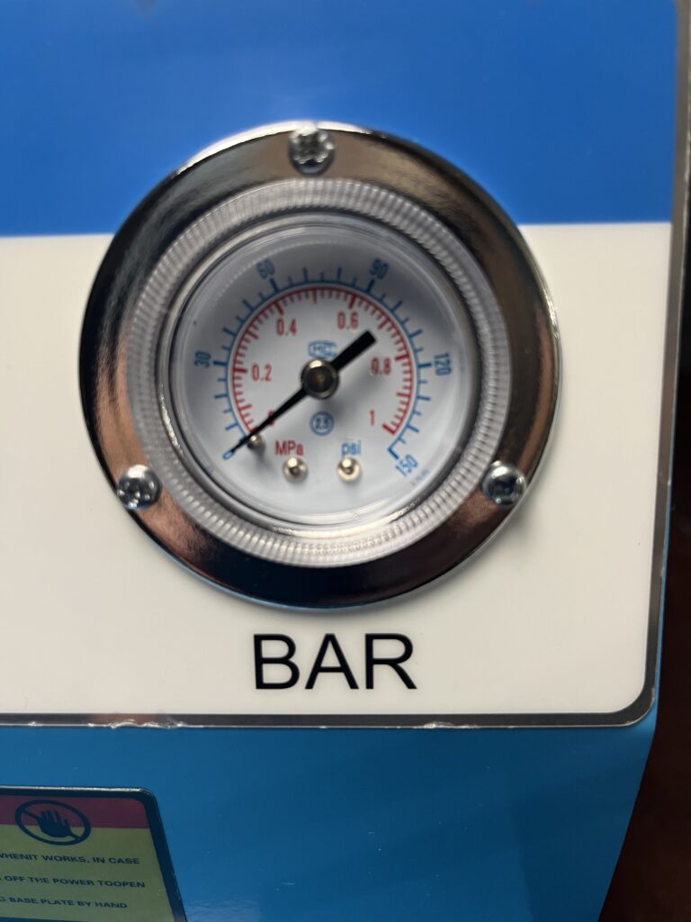
Pressure Gauge
The Workshop Ledger reference unit includes a round analog pressure gauge connected to the boiler-pressure system.
The gauge responds during boiler warm-up, steam use, pressure recovery, and shutdown, providing the operator with an external indication of system pressure.
The installed gauge displays pressure in both MPa and psi. No complete manufacturer or model identification has been established from the markings presently documented.
During repeated operation, the green pressure-ready indicator has illuminated at approximately 60 psi indicated pressure. Because the installed gauge has not been independently calibrated against a known reference, readings from it are documented as indicated pressure rather than verified absolute pressure.
No gauge failure has been documented during The Workshop Ledger ownership.
Identification & Specifications
Component Type: Analog pressure gauge
Manufacturer: Unresolved
Model / Part Number: Unresolved
Displayed Units: MPa and psi
Location: Externally mounted on the boiler cabinet
Measured Medium: Boiler steam/pressure system
Function: Indicates boiler-system pressure
Calibration Status: Unverified
Exact Accuracy: Unresolved
Identification Status: Function Confirmed / Identity Unresolved
The installed gauge has proven useful for documenting operating behavior of the reference unit, but its readings should not be used as calibrated test measurements until gauge accuracy has been independently evaluated.
Selection of a replacement gauge would require verification of pressure range, pressure connection and thread type, mounting dimensions, temperature capability, physical fit, and appropriate accuracy for the application.
Boiler Heating System
The boiler contains an electrically powered heating system that heats the contained water to generate steam and build boiler pressure.
Manufacturer-supplied documentation and the exterior specification label on The Workshop Ledger reference unit identify the boiler-heater rating as 1600 W at 110 V.
The reference unit has successfully heated water, generated steam, and built operating pressure, confirming the function of the installed boiler-heating system.
No manufacturer, model number, or part number for the installed heating element has been conclusively documented. Its exact physical configuration, resistance, and measured current draw also remain unresolved.
The boiler-heating system is electrically associated with the contactor, pressure-control system, thermal devices, and other portions of the boiler-control architecture. The complete electrical sequence among these components has not yet been established through terminal-by-terminal circuit tracing.
Identification & Specifications
Component Type: Electric boiler heating system
Manufacturer: Unresolved
Model / Part Number: Unresolved
Published Heater Rating: 1600 W
Published Supply Voltage: 110 V
Measured Heater Resistance: Not established
Measured Current Draw: Not established
Exact Element Configuration: Unresolved
Location: Directly associated with the pressure boiler
Function: Heats boiler water to generate steam
Identification Status: Function Confirmed / Identity Unresolved
The 1600 W value is a published and machine-labeled rating, not a direct electrical measurement of the installed heating element.
No boiler-heating-element failure has been documented during The Workshop Ledger ownership. A verified replacement cannot presently be specified because the electrical, dimensional, mounting, sealing, and connection requirements of the installed element have not been fully established.
Iron Heating System & Thermostat
The ST-750 iron contains an electrical heating element and adjustable thermostat system that heat and regulate the iron soleplate.
The exterior specification label on The Workshop Ledger reference unit identifies the iron-heater rating as 900 W at 110 V. The temperature-control assembly on the iron is also physically marked WATT 900 VOLT 110, providing direct component-level evidence of those ratings.
During operation, the iron heats successfully and adjustment of the rotary temperature-control dial affects heating behavior. The thermostat regulates soleplate heating according to the selected control position.
The iron heating system operates independently of individual steam-release commands. The iron can therefore remain electrically heated while steam delivery is controlled separately through the hand-operated steam control.
No complete manufacturer identification, heating-element part number, or thermostat model has been established. Exact soleplate temperatures corresponding to the temperature-control dial positions have also not yet been independently measured.
Identification & Specifications
Component Type: Electric iron heating element and adjustable thermostat system
Manufacturer: Unresolved
Heating-Element Part Number: Unresolved
Thermostat Model: Unresolved
Rated Iron-Heater Power: 900 W
Rated Supply Voltage: 110 V
Verified Soleplate Temperature Range: Not established
Location: Within the heated iron
Function: Heats and regulates the iron soleplate
Identification Status: Function Confirmed / Exact Component Identity Unresolved
The 900 W / 110 V ratings are supported both by the machine’s exterior specification label and markings physically present on the iron temperature-control assembly. They should not, however, be interpreted as measurements of actual electrical consumption during operation.
No failure of the iron heating system or thermostat has been documented during The Workshop Ledger ownership. A verified replacement heating element or thermostat cannot presently be specified because the installed components have not been positively identified.
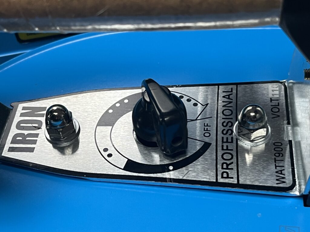
Iron Steam-Control Microswitch
The hand-operated steam control on the ST-750 iron mechanically actuates an internal microswitch.
During normal operation, pressing the hand control actuates this switch and results in steam delivery through the iron. The microswitch therefore forms the operator-input portion of the steam-control system and is functionally associated with electrical operation of the boiler-mounted steam solenoid valve.
Visible markings on the installed microswitch include G22 and additional electrical markings. The available evidence does not yet establish a complete manufacturer or model identification.
The complete electrical path between the iron microswitch and the P/N 145230 steam-solenoid valve has not been verified terminal by terminal.
Identification & Specifications
Component Type: Mechanically actuated electrical microswitch
Visible Marking: G22 / related markings
Manufacturer: Unresolved
Exact Model / Part Number: Unresolved
Contact Configuration: Unresolved
Location: Within the iron handle
Function: Provides the electrical command associated with hand-operated steam delivery
Identification Status: Partially Identified
The visible markings and physical installation establish the presence and function of the microswitch, but they are insufficient to specify a verified replacement.
Replacement would require confirmation of electrical ratings, contact configuration, actuator geometry, mounting dimensions, terminal arrangement, and compatibility with the iron’s hand-operated steam mechanism.
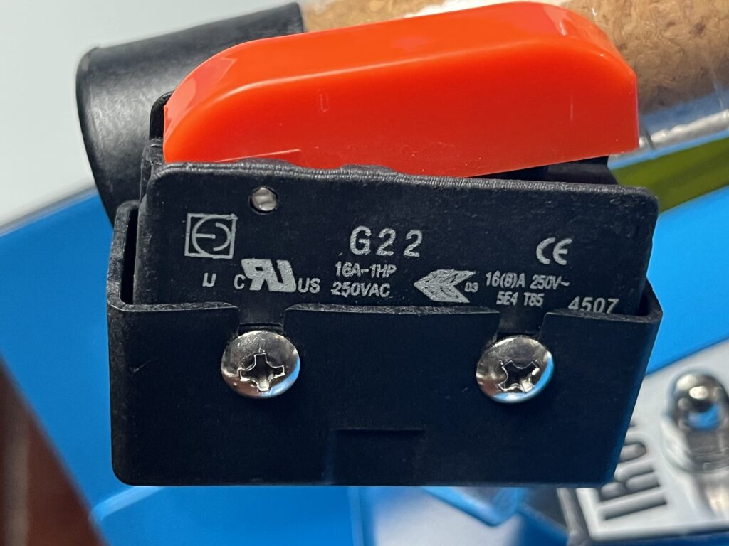
Barrier Terminal Strip
A barrier-style terminal strip is installed within the electrical/control area of The Workshop Ledger reference unit and provides fixed connection points for multiple internal electrical conductors.
The terminal strip forms part of the machine’s internal electrical distribution, providing mechanically secured connection points among portions of the boiler, controls, contactor, steam-control system, and other electrical components.
No complete manufacturer, model number, or electrical rating has been established for the installed terminal strip.
A complete terminal-by-terminal circuit map has not yet been produced. Accordingly, individual terminal functions should not be assigned solely from wire color, apparent routing, or physical proximity.
Identification & Specifications
Component Type: Barrier terminal strip
Manufacturer: Unresolved
Model / Part Number: Unresolved
Electrical Rating: Unresolved
Location: Internal electrical/control area
Function: Internal electrical connection and distribution
Identification Status: Function Confirmed / Identity Unresolved
The terminal strip has not been identified as the source of any observed machine fault.
Replacement, if ever required, would need to account for terminal count, conductor size, electrical rating, temperature environment, mounting arrangement, insulation, and physical dimensions.
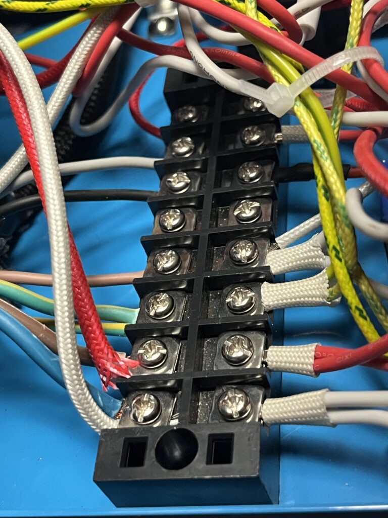
Boiler-Mounted Thermal Devices
Two round, metal-bodied thermal devices are mounted directly against the exterior of the insulated boiler on The Workshop Ledger reference unit.
Each device has two electrical terminals and is retained against the boiler by a metal mounting bracket. Their direct thermal contact with the boiler and their construction are consistent with temperature-responsive switching devices.
The precise function of each device has not yet been established. They may participate in normal temperature control, over-temperature protection, or both, but the available evidence does not justify assigning either device a specific role.
No legible manufacturer, model number, switching temperature, reset characteristic, or electrical rating has yet been documented from the installed devices. Their electrical relationships to the boiler heater, contactor, pressure-control system, and other protective devices also have not been established through terminal-by-terminal circuit tracing.
Identification & Specifications
Component Type: Boiler-mounted thermal switching/protection devices
Quantity: Two
Manufacturer: Unresolved
Model / Part Number: Unresolved
Switching Temperature: Unresolved
Reset Type: Unresolved
Electrical Rating: Unresolved
Location: Mounted directly against the insulated boiler exterior
Function: Temperature-responsive control and/or protection; exact individual functions unresolved
Identification Status: Physical Configuration Documented / Exact Functions and Identities Unresolved
Because these devices may perform safety-related functions, their operating temperatures or purposes should not be inferred solely from their appearance or mounting location.
A verified replacement cannot presently be specified. Positive identification would require additional markings, electrical circuit tracing, controlled functional testing, or removal sufficient to inspect markings that may be concealed by the mounting arrangement.
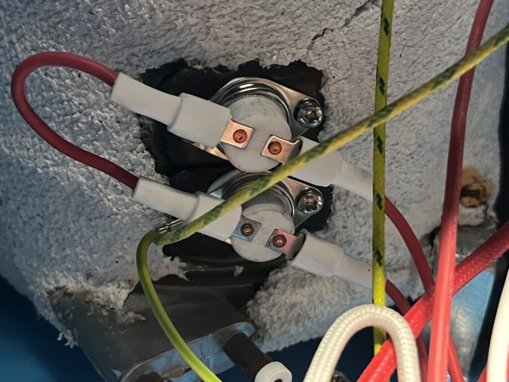
Boiler Heating-Element Connections
Electrical connections associated with the boiler heating system are located within the lower portion of the cabinet near the boiler.
Two insulated penetrations are visible at the lower boiler assembly and appear consistent with electrical connections serving an internally mounted heating element. Their physical location and construction support that interpretation, but the connections have not yet been electrically traced or otherwise positively identified as the boiler-heater terminals.
The exterior specification label identifies the boiler heater as 1600 W at 110 V, but no markings identifying the heating element itself or its terminal arrangement have been documented.
The wiring associated with these connections has not yet been traced sufficiently to establish polarity, switching path, conductor assignment, or the complete relationship among the heating element, contactor, pressure-control system, and boiler-mounted thermal devices.
Identification & Specifications
Component Type: Probable boiler heating-element electrical connections
Quantity: Two visible insulated penetrations
Heating-Element Manufacturer: Unresolved
Heating-Element Part Number: Unresolved
Published Boiler-Heater Rating: 1600 W
Published Supply Voltage: 110 V
Terminal Configuration: Unresolved
Conductor Assignment: Unresolved
Location: Lower portion of the boiler assembly
Function: Probable electrical connection to the internal boiler heating element
Identification Status: Probable Function / Not Electrically Verified
These connections should remain classified as probable rather than confirmed boiler-heater terminals until their electrical path is established.
Internal Wiring & High-Temperature Conductors
The ST-750 reference unit contains several types of internal electrical conductors selected for different portions of the machine’s electrical and thermal environment.
Visible wiring includes conventional insulated conductors, green-and-yellow protective-ground conductors, heavier red conductors with woven outer coverings, and white conductors enclosed in braided heat-resistant sleeving. Connections are distributed among the terminal strip, contactor, control components, boiler-mounted devices, and other internal assemblies.
The use of braided or otherwise heat-resistant covering is particularly evident on conductors routed near the boiler and other heated components. Individual conductor insulation materials, temperature ratings, wire gauges, and manufacturers have not been comprehensively identified.
Wire color alone should not be used to assign circuit function. The complete internal wiring system has not yet been traced terminal by terminal, and conductor functions documented in this Technical Reference are limited to those supported by physical or electrical evidence.
Inspection of The Workshop Ledger reference unit also revealed localized deterioration of a woven protective covering on at least one internal conductor or cable assembly. The covering is visibly frayed, exposing the insulated conductors beneath it. The available evidence does not establish that the underlying electrical insulation itself is damaged.
Identification & Specifications
System Type: Internal electrical wiring and conductor protection
Conductor Types Observed: Multiple insulated and heat-resistant/sleeved conductors
Protective-Ground Color: Green/yellow observed
Conductor Gauges: Not comprehensively established
Insulation Materials: Unresolved
Temperature Ratings: Unresolved
Circuit Assignments: Partially established
Observed Condition: Localized fraying/deterioration of one woven outer covering
Underlying Electrical Insulation at Frayed Area: No damage established from current evidence
Documentation Status: Physical Construction Documented / Complete Circuit Identification Unresolved
The frayed covering is documented because deterioration of protective sleeving can provide useful information about routing, abrasion, heat exposure, material durability, and long-term serviceability. Its presence should not, without additional evidence, be characterized as an electrical conductor failure.
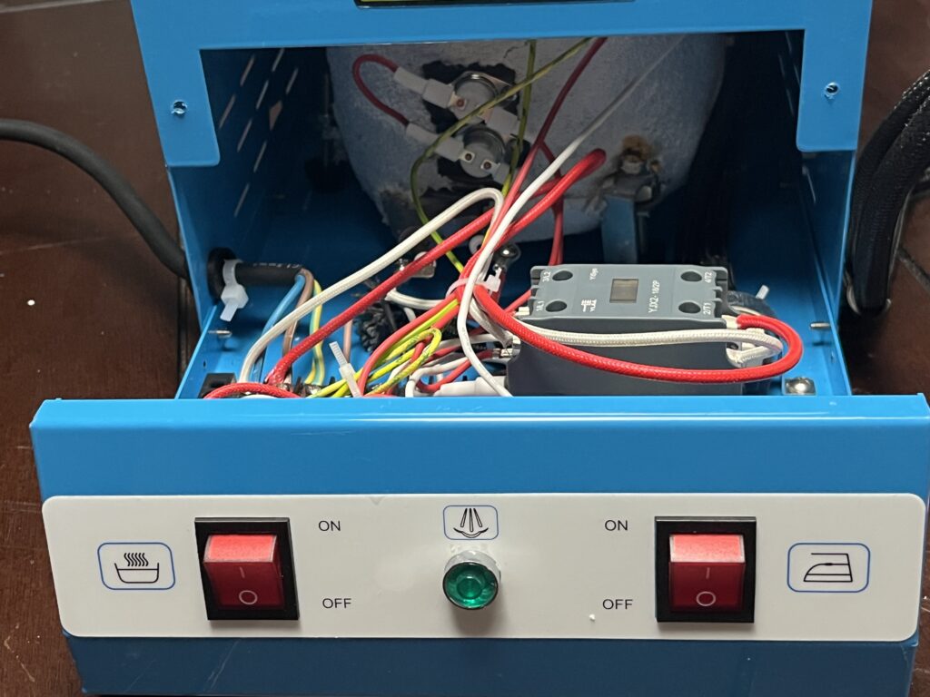
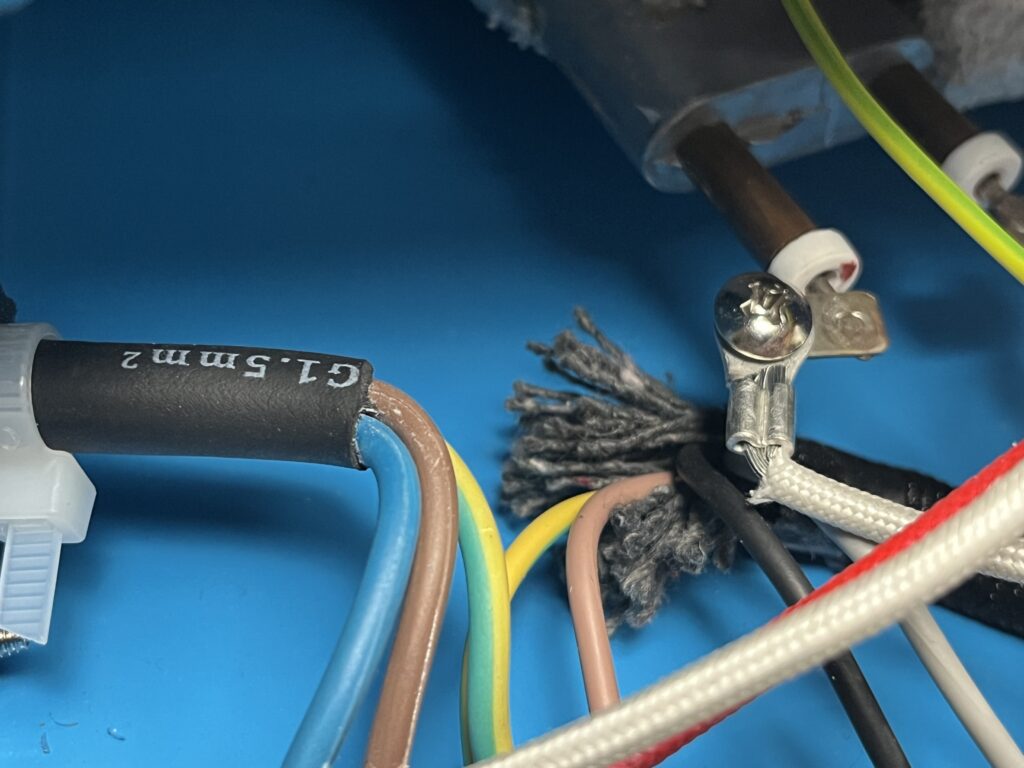
Protective Grounding System
The ST-750 reference unit incorporates protective grounding through green-and-yellow conductors visible within the cabinet.
These conductors are routed among electrically conductive portions of the machine and form part of the protective-grounding system intended to maintain exposed metal components at ground potential in the event of an electrical fault.
The incoming mains cable includes a green-and-yellow conductor, and additional green-and-yellow conductors are visible within the internal wiring assembly. Photographic evidence also shows grounding conductors routed toward the boiler and chassis areas.
The complete protective-ground path has not yet been traced or electrically tested. Continuity among the mains protective-ground conductor, cabinet, boiler, iron, and other exposed conductive components therefore should not be represented as independently verified.
Identification & Specifications
System Type: Protective electrical grounding
Conductor Identification: Green/yellow
Incoming Protective-Ground Conductor: Observed
Internal Ground Conductors: Observed
Cabinet Ground Continuity: Not independently tested
Boiler Ground Continuity: Not independently tested
Iron Ground Continuity: Not independently tested
Grounding Topology: Not completely traced
Documentation Status: Physical Grounding Conductors Confirmed / Electrical Continuity Unverified
The presence of protective-ground conductors provides physical evidence that grounding is incorporated into the machine’s electrical construction, but visual inspection alone cannot establish the integrity of the complete protective-ground path.
Boiler Electrical / Sensing Penetrations
Electrically insulated penetrations are installed in association with the boiler and connected into The Workshop Ledger reference unit’s internal control wiring.
Their electrical isolation from the boiler shell and relationship to the HB-BJ-1 electronic board support a possible sensing or monitoring function.
One plausible interpretation is that these penetrations participate in water-level sensing or low-water protection, but that function has not been conclusively established. They may instead perform another sensing or control function within the boiler system.
No manufacturer, part number, electrical operating principle, or authoritative documentation for the installed penetrations has yet been identified.
Their exact relationship to the HB-BJ-1 board also remains unresolved because the associated circuit has not been traced terminal by terminal.
Identification & Specifications
Component Type: Electrically insulated boiler penetrations / probable sensing components
Manufacturer: Unresolved
Model / Part Number: Unresolved
Location: Associated with the pressure boiler
Electrical Operating Principle: Unresolved
Exact Function: Unresolved
Possible Function: Water-level or low-water sensing
Relationship to HB-BJ-1 Board: Probable association; not completely traced
Identification Status: Unresolved / Possible Sensing Function
Water-level sensing remains a Probable interpretation rather than a confirmed identification. No individual penetration should be assigned a specific function until supported by circuit tracing, controlled testing, component identification, or authoritative documentation.
Establishing their function will be particularly important to determining whether the HB-BJ-1 board provides low-water warning, heater interruption, another protective function, or some combination of these.
Additional Protective or Control Devices
The ST-750 reference unit contains several electrical and electromechanical devices whose individual identities and system relationships remain only partially established.
These components may perform electrical protection, control, switching, or monitoring functions depending upon their individual application within the machine.
Where a component can be documented by location, physical relationship, or observed function without establishing its exact identity, that limited information is preserved elsewhere in this Technical Reference.
Exact manufacturer, model, ratings, and circuit function remain unresolved for components lacking sufficient identifying evidence.
No component is assigned a specific protective or control function solely from visual similarity to externally documented parts.
Measurements
This section records measurements taken directly from The Workshop Ledger ST-750 reference unit and published dimensions useful for comparison.
Direct measurements are distinguished from manufacturer-published values.
Approximate measurements should not be used for replacement-part selection where precise dimensions, thread identification, or interface geometry are required.
Overall Dimensions
The documentation supplied with The Workshop Ledger reference unit publishes the following overall dimensions and weight:
| Measurement | Published Value |
|---|---|
| Overall Dimensions | 405 × 235 × 290 mm |
| Approximate Imperial Equivalent | 16 × 9.2 × 11.4 in |
| Weight | 13 kg / 28.6 lb |
These are published values, not measurements made by The Workshop Ledger.
The orientation assigned to the three published dimensions has not been independently verified. The dimensions are therefore retained in their published order rather than relabeled as width × depth × height without supporting evidence.
Direct overall dimensions of the reference unit have not yet been recorded.
Component Measurements
Flexible Steam Hose
Measured Feature: Outside diameter
Measurement: 11.80 mm
Measurement Points: Exterior diameter of installed flexible steam hose
Method / Tool: Direct physical measurement
Conditions & Notes
This measurement establishes only the approximate exterior diameter of the installed hose.
It does not establish the internal diameter, wall thickness, reinforcement, working-pressure rating, temperature rating, or end-fitting dimensions.
Outside diameter alone is insufficient for selecting a replacement steam hose.
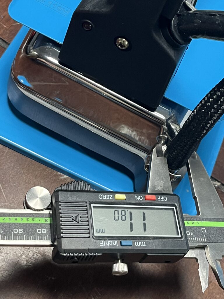
Steam Adjustment / Outlet Assembly
Measured Feature: Outside diameter of exposed threaded valve stem
Measurement: 12.17 mm
Measurement Points: Across the outside diameter of the exposed threads on the steam-adjustment valve stem
Method / Tool: Digital caliper
Conditions & Notes
The 12.17 mm measurement was taken across the outside diameter of the exposed threaded stem of the steam-adjustment valve.
This measurement documents the approximate major diameter of the installed threaded stem, but does not by itself establish the thread standard, thread pitch, or exact thread designation.
The measurement should therefore not be used alone for replacement-part or thread identification.
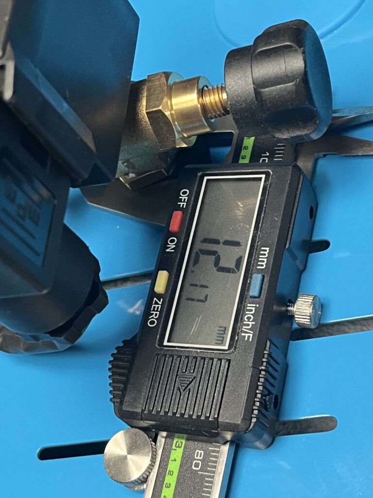
Connection & Fitting Measurements
No steam-system thread or fitting connection has yet been positively identified through sufficient direct measurement.
Approximate outside diameter alone is not sufficient to distinguish among similar metric, BSP, NPT, or other thread forms.
Current connection and fitting dimensions remain unresolved for components including:
- Steam outlet fittings
- P/N 145230 solenoid-valve ports
- Pressure-gauge connection
- Steam-hose end fittings
- Pressure-control connection
No thread standard is assigned to these connections in the current reference.
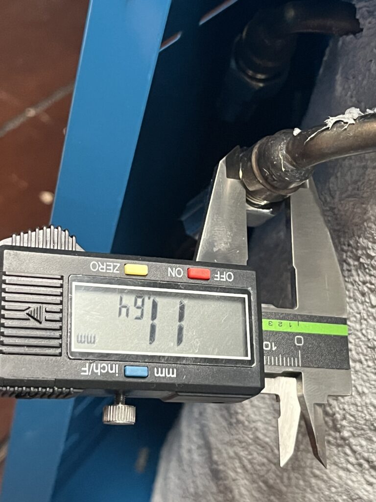
Published vs. Measured Dimensions
Overall Machine Dimensions
Published Dimension: 405 × 235 × 290 mm / approximately 16 × 9.2 × 11.4 in
Published Source: Documentation supplied with The Workshop Ledger reference unit
Reference Unit Measurement: Not independently measured
Difference / Notes: No direct comparison is presently available.
Steam Hose
Published Dimension: No hose diameter established in available supplied documentation
Reference Unit Measurement: 11.80 mm outside diameter
Difference / Notes: Direct measurement applies specifically to The Workshop Ledger reference unit.
Steam Adjustment / Outlet Assembly
Published Dimension: No corresponding published dimension established
Reference Unit Measurement: 12.17 mm outside diameter of exposed threaded valve stem
Difference / Notes: The measurement documents the outside diameter of the exposed threads but does not establish the thread standard or pitch.
Measurement Notes
Pressure, time, electrical-load, and other performance measurements are preserved in the applicable operating or Performance Testing records rather than duplicated here.
Current examples include:
- Approximately 60 psi indicated pressure associated with illumination of the green pressure-ready indicator
- 19 min 57.92 sec cold-start warm-up result documented as ST-750-TST-001 — Cold-Start Warm-Up Time
- Calculated electrical-current values derived from published heater ratings
- Observed breaker-trip behavior on a shared 15 A branch circuit
The installed pressure gauge has not been independently calibrated. Pressure readings from the machine are therefore described as indicated pressure.
Measurements not presently established remain unresolved unless and until they become useful for identification, operation, maintenance, troubleshooting, repair, replacement, or comparison.
Wiring & System Diagrams
The Workshop Ledger reference unit has been examined internally and several major electrical, control, pressure, and steam-system relationships have been established.
A complete terminal-by-terminal electrical trace has not been performed.
The diagrams in this section therefore distinguish between:
- Verified relationships supported directly by sufficient evidence
- Preliminary diagrams based on established components and incomplete circuit tracing
- Partial diagrams that intentionally document only part of a larger system
Unless specifically identified as Verified, the diagrams below are The Workshop Ledger-created functional representations and should not be interpreted as original manufacturer schematics.
No original manufacturer wiring diagram for The Workshop Ledger reference unit has been located.
Diagram Index
| Diagram Type | Type | Status |
|---|
| Preliminary Power Distribution | Functional Electrical Diagram | Preliminary |
| Boiler Heating / Control System | Functional Control Diagram | Preliminary |
| Pressure-Control System | Functional Control Diagram | Partial |
| HB-BJ-1 Monitoring / Protection System | Functional Control Diagram | Preliminary |
| Boiler Sensing Relationship | Functional Control Diagram | Preliminary |
| Steam-Control Electrical Sequence | Functional Control Diagram | Partial |
| Boiler-to-Iron Steam Path | Steam-System Diagram | Verified at functional level |
| Iron Heating System | Functional Electrical Diagram | Partial |
| Protective Grounding | Functional Electrical Diagram | Verified |
| Pressure-Gauge Path | Pressure / Steam Diagram | Verified |
Figure identifiers can be assigned when final diagrams or illustrations are prepared for publication.
Electrical Wiring
Preliminary Power Distribution
Diagram Type: Functional Electrical Diagram
Status: Preliminary
Basis
Direct internal examination establishes separate boiler and iron controls and visibly distinct electrical paths.
[Diagram pending — Preliminary Power Distribution]
Notes
The reference unit contains:
- Incoming mains supply
- Protective grounding
- Barrier terminal strip
- Separate front-panel boiler and iron controls
- YJX2-18/2P contactor
- Boiler heating system
- Iron heating system
- Pressure-control components
- HB-BJ-1 electronic board
- Steam-solenoid circuit
A complete terminal-by-terminal electrical circuit has not been established.
No verified conclusion can yet be made that the machine electrically prevents the boiler heater and iron heater from operating simultaneously.
Boiler & Iron Load Relationship
Diagram Type: Functional Electrical Diagram
Status: Preliminary
The supplied documentation publishes:
| Load | Published Power |
|---|---|
| Boiler Heater | 1600 W |
| Iron Heater | 900 W |
| Arithmetic Combined Heating Load | 2500 W |
The combined 2500 W value is an arithmetic total of the two published ratings. It is not a measured operating load.
The available physical evidence supports independent boiler and iron control branches but does not conclusively establish whether their heating elements can be energized simultaneously.
A possible independent-load arrangement is represented in the preliminary diagram below.
[Diagram pending — Boiler & Iron Load Relationship]
Status of this arrangement: Probable, not verified.
No component or wiring relationship establishing automatic load shedding between the boiler and iron has been identified.
The actual load relationship remains unresolved.
Protective Grounding
Diagram Type: Functional Electrical Diagram
Status: Verified
Basis
Direct examination confirms a protective-earth conductor bonded to the metal chassis.
[Diagram pending — Protective Grounding]
Ground continuity has not been documented through electrical measurement.
Control System
Boiler Heating / Control System
System: Boiler electrical-control system
Status: Preliminary
Basis
Direct examination confirms the presence of:
- Boiler heating system
- YJX2-18/2P contactor
- Pressure-control assembly
- D45X microswitch
- Boiler-mounted thermal devices
- HB-BJ-1 board
- Front-panel boiler control
- Associated wiring
[Diagram pending — Boiler Heating / Control System]
Boiler pressure is monitored mechanically by the pressure-control assembly.
The pressure-control mechanism actuates the D45X microswitch.
The YJX2-18/2P contactor is associated with switching the high-current boiler-heater circuit.
Boiler-mounted thermal devices and the HB-BJ-1 system are also electrically associated with the boiler-control architecture.
Notes
The exact series or parallel relationships among:
- Boiler rocker switch
- D45X microswitch
- Boiler-mounted thermal devices
- HB-BJ-1 board
- Contactor coil
These relationships have not been established.
The installed contactor coil voltage also remains unresolved.
Pressure-Control System
System: Boiler pressure control
Status: Partial
Basis
The physical pressure pathway and mechanical actuation of the D45X microswitch are established directly.
[Diagram pending — Pressure-Control System]
Functional Sequence
Boiler pressure acts upon the mechanical pressure-control assembly.
Mechanical movement within the assembly actuates the D45X microswitch.
Notes
The downstream electrical path from the D45X switch has not been completely traced.
Pressure-control cut-in and cut-out values have not been independently measured.
The approximately 60 psi indicated green ready-light threshold should not automatically be interpreted as a pressurestat cut-in or cut-out value.
HB-BJ-1 Monitoring / Protection System
System: Probable boiler monitoring / protection
Status: Preliminary
Basis
The installed HB-BJ-1 board includes:
- POWER connection
- INPUT connection
- Two LED positions
- Piezoelectric buzzer
- AC220V or 110V marking
The board is physically associated with the boiler-control system and boiler sensing components.
[Diagram pending — HB-BJ-1 Monitoring / Protection System]
Functional Sequence
The exact operating sequence has not been established.
Water-level monitoring / low-water protection remains the leading interpretation of the system.
Notes
It remains unresolved whether the HB-BJ-1:
- Monitors water level
- Provides visual warning
- Provides audible warning
- Interrupts or inhibits boiler heating
- Performs multiple monitoring or protective functions
Any heater-interlock relationship remains intentionally unresolved.
Boiler Sensing Relationship
System: Boiler-associated electrical sensing
Status: Preliminary
Basis
Insulated electrical penetrations are present at the boiler and appear electrically associated with the control system.
[Diagram pending — Boiler Sensing Relationship]
Notes
Water-level sensing is the leading interpretation.
It has not been established whether:
- The penetrations are conductivity electrodes
- The boiler body participates in the sensing circuit
- All penetrations serve the same function
- The system directly connects to HB-BJ-1 INPUT
- The sensing system inhibits boiler heating
The components therefore remain unresolved beyond their observed physical and electrical relationships.
Steam-Control Electrical Sequence
System: Operator-controlled steam delivery
Status: Partial
Basis
Direct operation establishes that the hand control on the iron commands steam delivery. The iron contains a mechanically actuated microswitch, and the boiler cabinet contains a P/N 145230 steam solenoid in the steam path.
[Diagram pending — Steam-Control Electrical Sequence]
Functional Sequence
The operator actuates the hand control.
The hand control mechanically operates the iron microswitch.
The electrical steam-control system operates the solenoid valve.
Steam is then delivered through the hose and iron.
Notes
The complete conductor path between the iron microswitch and solenoid has not been traced terminal by terminal.
Iron Heating System
System: Iron temperature control
Status: Partial
Basis
The iron heats successfully and includes an adjustable thermostat system.
[Diagram pending — Iron Heating System]
Functional Sequence
The thermostat controls electrical heating of the iron soleplate according to the selected temperature setting.
The iron’s steam-control microswitch performs a separate function from the iron thermostat.
Notes
Detailed internal iron wiring has not been fully documented.
Mechanical / Fluid / Steam Systems
Boiler-to-Iron Steam Path
System Type: Steam
Status: Verified at the functional level
Basis
Direct examination establishes the physical relationship among the boiler, steam plumbing, solenoid valve, hose, and iron.
[Diagram pending — Boiler-to-Iron Steam Path]
System Path / Sequence
Water is heated within the boiler to generate steam.
Steam passes from the boiler through the internal steam-control plumbing and P/N 145230 solenoid valve.
The steam then travels through the flexible hose to the iron.
Actuation of the iron steam control commands the electrically operated steam-delivery system.
Notes
The exact quantitative effect of the external steam-adjustment control has not been established.
Pressure-Gauge Path
System Type: Pressure / Steam
Status: Verified
Basis
The installed analog gauge is physically connected to the boiler-pressure system.
[Diagram pending — Pressure-Gauge Path]
System Path / Sequence
Boiler pressure is communicated to the installed analog gauge through the pressure connection.
The gauge provides operator-visible pressure indication.
Notes
Gauge calibration has not been independently verified.
Diagram Verification Notes
The diagrams in this section are based on combinations of:
- Direct physical examination
- Internal photography
- Visible component markings
- Observed operating behavior
- External component documentation
- Established mechanical and steam-system relationships
They are not original manufacturer schematics.
The following major electrical relationships remain incomplete:
- Exact incoming line and neutral routing
- Complete barrier-terminal-strip map
- Installed YJX2-18/2P contactor coil voltage
- Complete contactor-coil control path
- Exact electrical placement of the D45X pressure-control microswitch
- Exact electrical placement and functions of the boiler-mounted thermal devices
- Exact HB-BJ-1 POWER and INPUT relationships
- Exact relationship between HB-BJ-1 and boiler heating
- Complete P/N 145230 solenoid electrical path
- Complete iron steam-control microswitch circuit
- Complete iron heating circuit
- Whether boiler and iron heating elements can operate simultaneously
These unresolved relationships limit the electrical diagrams to Preliminary or Partial status where identified.
The verified physical and functional relationships documented here remain useful for understanding operation, maintenance, troubleshooting, and component relationships without implying a level of electrical verification that has not been achieved.
Any diagram created by The Workshop Ledger should be identified as independently documented unless it reproduces an authenticated manufacturer schematic.
Safety
The ST-750 combines mains-voltage electrical equipment, a heated iron, a heated pressure vessel, pressurized steam, hot water, and high-temperature plumbing within a compact system.
Safe operation therefore depends on both the instructions supplied with the equipment and precautions appropriate to the observed construction and operating behavior of The Workshop Ledger reference unit.
Manufacturer-supplied safety information is distinguished below from safety guidance developed by The Workshop Ledger.
Manufacturer Safety Information
The documentation supplied with The Workshop Ledger reference unit contains operating and safety guidance concerning electrical power, boiler filling, steam pressure, hot surfaces, and shutdown.
The following summarizes the safety information relevant to normal operation.
Electrical Supply
Source: Documentation supplied with the reference unit
Applies To: Boiler and iron electrical systems
Safety Information
The equipment is intended for operation from the electrical supply specified for the machine.
Electrical connections, cords, plugs, switches, and other electrical components should remain in serviceable condition.
The equipment should not be operated with visibly damaged electrical components.
Boiler Filling
Source: Documentation supplied with the reference unit
Applies To: Boiler filling and operation
Safety Information
The boiler must contain an appropriate quantity of water before heating.
The fill opening should be securely closed before the boiler is pressurized.
The boiler should not be opened while pressurized.
The supplied documentation identifies a nominal boiler capacity of 4 L.
The documentation available to The Workshop Ledger does not establish that 4 L represents the recommended normal operating fill quantity.
Pressurized Steam
Source: Documentation supplied with the reference unit
Applies To: Boiler, steam hose, iron, fittings, and steam-control system
Safety Information
Steam and pressurized hot water can cause serious burns.
The boiler, hose, fittings, and iron should be treated as pressurized and hot during operation.
The boiler fill cap should not be removed while the system is pressurized.
Heated Iron and Hot Surfaces
Source: Documentation supplied with the reference unit
Applies To: Iron and other heated components
Safety Information
The iron reaches temperatures capable of causing burns and damaging heat-sensitive materials.
Contact with the heated soleplate should be avoided.
The iron should be placed in a stable position when not actively being used.
Shutdown and Depressurization
Source: Documentation supplied with the reference unit
Applies To: Boiler and steam system
Safety Information
The equipment should be switched off after use and allowed to cool and depressurize before opening or servicing the boiler system.
The Workshop Ledger Safety Notes
The following safety notes are based on direct examination, operation, testing, and documented behavior of The Workshop Ledger reference unit.
They supplement rather than replace the safety information supplied with the equipment.
Electrical Demand
Applies To: Electrical supply and branch circuit
Hazard
The supplied documentation publishes a 1600 W boiler heater and 900 W iron heater.
If both heating loads can operate simultaneously, their arithmetic combined load is approximately 2500 W.
At a nominal 110 V:
- 1600 W corresponds to approximately 14.5 A
- 900 W corresponds to approximately 8.2 A
- 2500 W corresponds to approximately 22.7 A
These values are calculated from published wattage ratings and are not direct current measurements of The Workshop Ledger reference unit.
The reference unit repeatedly tripped a shared 15 A branch-circuit breaker during operation when other equipment was also connected to that circuit.
The exact electrical relationship between the boiler and iron heaters remains unresolved, and simultaneous heater operation has not been directly confirmed.
Precaution
The ST-750 should not be treated as a low-demand appliance.
The electrical circuit supplying the machine should be appropriate for the actual connected load and installation.
Repeated breaker trips should not be defeated by substituting a larger breaker without first establishing that the branch-circuit wiring, receptacle, plug, equipment, and applicable electrical requirements support the change.
Basis
- Published heater ratings
- Internal electrical examination
- Repeated shared-circuit breaker trips
- ST-750-OBS-004 — Shared 15 A Branch-Circuit Breaker Trips
Boiler Fill Level and Water Carryover
Applies To: Boiler filling and steam delivery
Hazard
A substantially higher boiler fill than the approximately 2 L used during the initial successful operating session produced significant liquid-water carryover and sputtering from the iron.
Discharge of hot liquid water from the iron presents a burn hazard and can wet or damage the workpiece.
Precaution
The published 4 L nominal boiler capacity should not be assumed to be the normal operating fill quantity.
Until a manufacturer-recommended operating fill range is established, fill level should be approached conservatively and the behavior of the machine observed during steam delivery.
If significant liquid-water sputtering occurs, steam application should be stopped until the cause is addressed.
Basis
- Direct operation of The Workshop Ledger reference unit
- ST-750-OBS-003 — High Fill-Level Water Carryover
Pressure Indication
Applies To: Boiler-pressure monitoring
Hazard
The installed pressure gauge has not been independently calibrated.
Treating its indicated value as a verified absolute pressure could create false confidence concerning actual boiler pressure.
Precaution
Pressure values documented from the installed gauge should be treated as indicated pressure unless calibration is established.
The approximately 60 psi indicated green ready-light behavior is an operating observation and should not be interpreted as a verified safety limit or pressurestat setting.
Basis
- Direct operation
- Uncalibrated installed gauge
- ST-750-OBS-002 — Green Pressure-Ready Indicator Behavior
Unresolved Protective Devices
Applies To: Boiler heating and protective-control system
Hazard
The reference unit contains boiler-mounted thermal devices, an HB-BJ-1 electronic board, and boiler-associated sensing components whose exact functions and ratings remain unresolved.
Assuming that an unidentified device provides a particular protective function could result in unsafe troubleshooting or operation.
Precaution
Unverified components should not be bypassed, defeated, substituted, or assigned specific protective functions without sufficient evidence.
Basis
- Internal examination
- Component research
- Internal Tour, Component Reference, and Wiring & System Diagrams portions of this Technical Reference
Electrical Safety
The ST-750 contains mains-voltage wiring and high-current heating loads.
Electrical hazards remain present inside the cabinet even though the machine’s exterior controls operate normally.
Important electrical considerations include:
- Protective grounding of the metal chassis
- Condition of the mains cord and plug
- Condition of the iron electrical lead
- Secure electrical terminals
- Heat-resistant insulation near the boiler
- Condition of the contactor and terminal strip
- Separation of electrical wiring from hot or leaking steam components
- Appropriate branch-circuit capacity
The internal chassis includes a visible protective-earth connection.
Ground continuity has not been independently measured.
The machine should be disconnected from electrical power before the cabinet is opened for inspection or service.
Stored heat and pressure may remain after electrical power has been removed.
A tripped branch-circuit breaker is a protective event. Repeated tripping should be investigated rather than defeated.
Pressure / Steam Safety
The boiler stores hot water and steam under pressure.
Pressurized steam can cause severe burns, and pressure may remain after electrical power has been switched off.
The following conditions require particular caution:
- Removing the boiler fill cap
- Disconnecting steam fittings
- Removing the pressure gauge
- Servicing the pressure-control assembly
- Servicing the steam solenoid valve
- Disconnecting the steam hose
- Opening any boiler-connected plumbing
The boiler fill cap should not be removed while the system is pressurized.
Loss of electrical power does not immediately eliminate stored pressure.
The pressure gauge can provide useful indication of remaining pressure, but because it has not been independently calibrated, the gauge should not be treated as the sole means of proving that the system is safe to open.
Steam should be directed away from the operator and bystanders during use.
Unexpected discharge of liquid water should be treated as abnormal behavior rather than normal steam delivery.
Thermal Safety
Multiple ST-750 components become hot during operation.
These include:
- Iron soleplate
- Boiler
- Steam plumbing
- Solenoid-valve area
- Steam hose and fittings
- Boiler-connected pressure components
- Water or condensate discharged from the iron
Some internal components may remain hot after the machine is switched off.
The iron should be placed securely when not actively being used.
Heat-resistant internal wiring and sleeving should not be assumed to make adjacent components safe to touch during or immediately after operation.
Cooling time should be allowed before internal inspection or service.
Mechanical Safety
The ST-750 contains relatively few externally exposed moving mechanical parts, but several mechanical hazards remain relevant.
Potential hazards include:
- Pinch points associated with switches and controls
- Mechanical movement within the pressure-control assembly
- Accidental movement or dropping of the heated iron
- Damage caused by pulling or lifting the machine by the steam hose or electrical leads
- Loosening of pressurized fittings during inappropriate service
The iron, steam hose, and electrical lead should be positioned so that normal movement during hat work does not pull the machine, strain connections, or cause the iron to fall.
Service and Maintenance Safety
Before internal inspection, adjustment, repair, or component replacement:
- Disconnect the machine from electrical power.
- Allow the iron and boiler system to cool.
- Allow the boiler to depressurize.
- Treat boiler-connected plumbing as potentially pressurized until safe conditions have been established.
- Avoid bypassing unidentified protective or control devices.
- Preserve protective grounding and heat-resistant wiring arrangements.
- Verify replacement-component compatibility before installation.
Service involving the boiler, steam fittings, pressure controls, electrical heating circuits, or protective devices requires particular care because an incorrect repair can affect both pressure and electrical safety.
The boiler’s maximum allowable working pressure and pressure-test rating have not been established.
No pressure-control adjustment should therefore be made on the assumption that a higher operating pressure is safe simply because the control can physically be adjusted.
Safety Limitations / Unresolved Information
Several safety-related characteristics remain unresolved for The Workshop Ledger reference unit:
- Boiler maximum allowable working pressure
- Boiler pressure-test rating
- Exact pressure-control cut-in pressure
- Exact pressure-control cut-out pressure
- Pressure-control differential
- Calibration accuracy of the installed pressure gauge
- Exact function and temperature ratings of the boiler-mounted thermal devices
- Exact function of the HB-BJ-1 electronic board
- Exact function of the boiler electrical/sensing penetrations
- Whether the HB-BJ-1 system interrupts boiler heating under a fault or low-water condition
- Installed YJX2-18/2P contactor coil voltage
- Exact electrical relationship between boiler and iron heating loads
- Whether the boiler and iron heating elements can operate simultaneously
- Manufacturer-recommended normal boiler operating fill range
These unresolved characteristics should not be replaced with assumptions merely because similar equipment uses a particular value or protective arrangement.
Where uncertainty affects safe operation or service, the Technical Reference retains that uncertainty explicitly.
Operation
This section documents practical operation of the ST-750 using the documentation supplied with The Workshop Ledger reference unit, direct experience operating the reference unit, and operating behavior established through testing and observation.
Where the supplied documentation and direct experience do not establish a procedure or operating limit, that information remains identified as unresolved.
The published 4 L boiler capacity should not be interpreted as an established normal operating fill quantity. The first successful operation of The Workshop Ledger reference unit used approximately 2 L of distilled water, while a later substantially higher fill produced significant liquid-water carryover from the iron.
Before Use
Before operating the ST-750:
- Place the machine on a stable work surface.
- Inspect the mains power cord, plug, iron electrical lead, steam hose, and visible fittings for obvious damage.
- Confirm that the boiler is cool and not pressurized before opening the fill cap.
- Confirm that the boiler contains an appropriate quantity of water.
- Securely reinstall the boiler fill cap before heating.
- Confirm that the iron is positioned securely.
- Connect the machine to an electrical supply appropriate for the equipment and connected load.
The Workshop Ledger reference unit has been successfully operated using approximately 2 L of distilled water.
This quantity is documented as a successful operating condition, not as a manufacturer-established required fill quantity.
The supplied documentation identifies a nominal boiler capacity of 4 L, but the manufacturer-recommended normal operating fill range has not been established.
A substantially higher fill during later operation produced significant liquid-water sputtering from the iron.
Related Record: ST-750-OBS-003 — High Fill-Level Water Carryover
Startup / Initial Setup
A practical startup sequence established with The Workshop Ledger reference unit is:
- Fill the cool, depressurized boiler with an appropriate quantity of water.
- Securely install the boiler fill cap.
- Connect the machine to electrical power.
- Switch on the boiler system.
- Switch on the iron system when iron heating is required.
- Set the iron temperature control appropriate to the work being performed.
- Allow the boiler to heat and build pressure.
- Monitor the pressure gauge and front-panel indicators during warm-up.
- Allow the iron to reach the selected operating temperature.
- Test steam delivery away from the workpiece before beginning hat work.
During the first documented cold start, The Workshop Ledger reference unit reached its observed ready condition in:
19 min 57.92 sec
Related Record: ST-750-TST-001 — Cold-Start Warm-Up Time
The installed green pressure-ready indicator repeatedly illuminates at approximately 60 psi indicated pressure.
Because the installed pressure gauge has not been independently calibrated, this value is an indicated operating observation rather than a verified absolute pressure.
Related Record: ST-750-OBS-002 — Green Pressure-Ready Indicator Behavior
Normal Operation
Boiler Heating and Pressure
Purpose: Generate and maintain steam pressure.
Procedure / Behavior
With the boiler system energized, the boiler heating system heats the contained water and pressure rises.
The installed pressure-control system regulates boiler heating in response to pressure.
During observed operation, the machine builds pressure and subsequently recovers pressure after steam use.
Relevant Indicators / Measurements
- Analog pressure gauge
- Front-panel indicators
- Green ready indicator at approximately 60 psi indicated
Notes
Exact pressure-control cut-in and cut-out values have not been independently measured.
The green ready-light threshold should not automatically be interpreted as either the pressurestat cut-in or cut-out pressure.
Iron Heating
Purpose: Heat the iron soleplate for pressing, shaping, and steam-assisted work.
Procedure / Behavior
The iron heating system is controlled separately from the boiler system.
The rotary temperature control regulates the iron’s internal thermostat.
The iron cycles heating as necessary to maintain the selected temperature range.
Relevant Indicators / Measurements
No direct soleplate-temperature measurements have been recorded.
Notes
Exact soleplate temperatures corresponding to individual dial positions remain unresolved.
The published iron-heater rating is 900 W.
Steam Delivery
Purpose: Deliver controlled steam through the heated iron.
Procedure / Behavior
Once the boiler has developed usable pressure, the hand-operated steam control on the iron can be actuated.
Actuation of the control operates the iron-handle microswitch and commands the steam-control system.
The P/N 145230 solenoid valve is associated with opening the steam path from the boiler toward the iron.
Steam then travels through the flexible steam hose and is discharged through the iron.
Relevant Indicators / Measurements
Boiler pressure decreases during sustained steam use and subsequently recovers as the boiler heating system restores pressure.
Notes
Steam should be tested away from the workpiece after startup or following a significant change in operating conditions.
Significant discharge of liquid water rather than steam is abnormal behavior and may indicate excessive boiler fill or another steam-delivery condition requiring investigation.
Pressure Recovery
Purpose: Restore boiler pressure after steam use.
Procedure / Behavior
Steam use reduces boiler pressure.
The pressure-control system allows the boiler heating system to restore pressure as required.
During operation of The Workshop Ledger reference unit, the green pressure-ready indicator extinguishes following sufficient pressure reduction and re-illuminates as pressure recovers to approximately 60 psi indicated.
Relevant Indicators / Measurements
- Pressure gauge
- Green pressure-ready indicator
Notes
The exact pressure at which boiler heating begins or ends has not been independently established.
Normal Operating Behavior
The following behaviors have been observed during normal operation of The Workshop Ledger reference unit:
- Boiler pressure rises during warm-up.
- The pressure gauge responds continuously to changes in boiler pressure.
- The green pressure-ready indicator illuminates at approximately 60 psi indicated.
- The green indicator can extinguish after sufficient steam use reduces boiler pressure.
- The green indicator re-illuminates as pressure recovers to approximately the same indicated value.
- Actuation of the iron steam control produces steam delivery.
- Sustained steam use reduces indicated boiler pressure.
- Boiler pressure subsequently recovers.
- The iron heats independently of individual steam-release commands.
- The iron thermostat regulates soleplate heating according to the selected control position.
These behaviors provide useful operating baselines for distinguishing normal operation from possible faults.
The exact internal electrical sequence responsible for every observed indicator and control behavior has not been fully verified.
Operating Adjustments
Iron Temperature
Control / Location: Rotary temperature-control dial on iron
Function: Adjusts the iron thermostat setting.
Adjustment / Range: Adjustable through the marked control range.
Observed Effect: Changes iron heating behavior and resulting soleplate temperature.
Notes
Exact temperatures corresponding to individual control positions have not been independently measured.
Steam Adjustment
Control / Location: External steam-adjustment control
Function: Adjusts steam delivery available through the iron.
Adjustment / Range: Adjustable; exact quantitative range not established.
Observed Effect: Affects steam delivery during operation.
Notes
The relationship between control position and steam flow has not been quantitatively measured.
No unsupported flow values are assigned to the control.
Boiler Fill Quantity
Boiler water quantity materially affects operation, but the fill quantity should not be treated as a normal operating adjustment in the same manner as iron temperature or steam flow.
The first successful operating session used approximately 2 L of distilled water.
A later substantially higher fill produced significant liquid-water carryover.
The exact recommended operating fill range remains unresolved.
Operating Problems / Abnormal Behavior
Liquid Water Sputtering From Iron
Observed Behavior
Significant liquid-water carryover and sputtering occurred during steam delivery following a substantially higher boiler fill.
Immediate Response
Stop applying steam to the workpiece.
Allow the machine to reach a safe condition before addressing boiler water quantity or other possible causes.
Related Record
- Troubleshooting
- ST-750-OBS-003 — High Fill-Level Water Carryover
Branch-Circuit Breaker Trip
Observed Behavior
The reference unit repeatedly tripped a shared 15 A branch-circuit breaker while operating on a circuit that also supplied other electrical loads.
Immediate Response
Stop operation and determine the electrical loading of the circuit rather than repeatedly resetting the breaker and continuing operation unchanged.
Do not substitute a larger breaker unless the entire branch circuit and installation have been established as appropriate for that rating.
Related Record
- Safety
- Troubleshooting
- ST-750-OBS-004 — Shared 15 A Branch-Circuit Breaker Trips
Failure to Build Pressure
Observed Behavior
Boiler pressure does not rise normally after startup.
Immediate Response
Switch off the machine if normal heating or pressure behavior is not occurring.
Do not adjust the pressure-control system or bypass protective devices as an initial response.
Related Record
- Troubleshooting
Failure to Deliver Steam
Observed Behavior
The boiler has developed pressure but actuation of the iron steam control does not produce normal steam delivery.
Immediate Response
Stop steam-dependent work and investigate the steam-control and delivery system.
Related Record
- Troubleshooting
- Wiring & System Diagrams
Pausing / Temporary Shutdown
For a brief pause in work, the iron should be placed securely so that the heated soleplate cannot contact the work surface, cords, steam hose, or other heat-sensitive materials.
The machine remains hot and may remain pressurized while energized or after heating has stopped.
Whether the boiler or iron should remain energized during an extended pause depends on the expected duration of the interruption and the operating needs of the work.
No manufacturer-defined temporary-idle procedure has been established from the documentation currently available.
For an extended interruption, normal shutdown is the more conservative procedure.
Shutdown
A practical shutdown sequence for The Workshop Ledger reference unit is:
- Stop active steam application.
- Switch off the boiler heating system.
- Switch off the iron heating system.
- Disconnect electrical power when the machine will no longer be used.
- Place the iron securely while it cools.
- Allow the boiler and steam system to depressurize naturally.
- Allow heated components to cool before handling, opening, draining, or servicing the machine.
The boiler fill cap should not be removed while the system remains pressurized.
Electrical shutdown does not immediately eliminate stored pressure or retained heat.
Restarting
Restart behavior depends upon the condition of the machine when operation resumes.
A recently used ST-750 may retain:
- Hot boiler water
- Boiler pressure
- Heat in the iron
- Heat in steam plumbing and fittings
Accordingly, a warm restart may require less time than a cold start.
Before restarting:
- Confirm that the boiler contains an appropriate quantity of water.
- Confirm that the fill cap is secure.
- Confirm that the machine remains in safe operating condition.
- Observe existing boiler pressure before energizing the heating system.
- Allow the iron to return to the desired working temperature.
- Test steam delivery away from the workpiece if operating conditions have changed.
The 19 min 57.92 sec result from ST-750-TST-001 applies to the documented cold-start test conditions and should not be treated as the expected warm-restart time.
Operating Limitations / Unresolved Information
The following operating information remains unresolved:
- Manufacturer-recommended normal boiler operating fill range
- Exact relationship between boiler fill quantity and steam quality
- Exact pressure-control cut-in pressure
- Exact pressure-control cut-out pressure
- Pressure-control differential
- Accuracy of the installed pressure gauge
- Exact pressure represented by the green pressure-ready indicator
- Exact soleplate temperatures corresponding to iron temperature-control positions
- Quantitative relationship between steam-adjustment position and steam output
- Whether the boiler and iron heating elements can operate simultaneously
- Exact electrical demand under each operating condition
- Exact function of the HB-BJ-1 electronic board
- Exact response of the machine to a verified low-water condition
- Manufacturer-defined temporary-idle procedure
These unresolved items do not prevent documentation of the operating behavior already established with The Workshop Ledger reference unit.
They should not, however, be replaced by assumptions derived solely from superficially similar steam boilers or irons.
Maintenance
The available manufacturer documentation does not establish a comprehensive preventive-maintenance schedule. Accordingly, The Workshop Ledger does not assign unsupported service intervals.
This section documents maintenance practices relevant to the ST-750 based on the documentation supplied with The Workshop Ledger reference unit, direct examination of the machine, and operating experience with the reference unit.
Maintenance requirements that remain unresolved are identified as such rather than inferred from superficially similar equipment.
Manufacturer Maintenance Information
The documentation supplied with The Workshop Ledger reference unit provides limited maintenance information. No comprehensive manufacturer service schedule, preventive-maintenance interval chart, or detailed service manual has been identified.
Water and Boiler Care
Source: Documentation supplied with the reference unit
Interval / Condition: During normal filling and operation
The boiler requires an appropriate quantity of water for steam generation. Although the supplied documentation identifies a nominal boiler capacity of 4 L, it does not establish:
- A manufacturer-recommended normal operating fill range
- A boiler flushing interval
- A descaling interval
- A specified descaling chemical or procedure
- A water-treatment schedule
The Workshop Ledger reference unit has been operated using distilled water. This is an ownership practice and should not be represented as a manufacturer requirement unless supporting documentation is established.
Iron and Steam System
Source: Documentation supplied with the reference unit
Interval / Condition: As required for normal operation
The iron, steam hose, and associated connections should remain in serviceable condition.
No detailed manufacturer procedure for internal iron cleaning, steam-path cleaning, hose replacement, or solenoid-valve maintenance has been established from the documentation currently available.
Routine Inspection
Routine inspection should focus on conditions that can materially affect safe or reliable operation. No fixed inspection interval has been established.
Electrical Cords and Leads
Inspect the mains power cord, plug, and iron electrical lead for:
- Cuts, abrasion, or cracking
- Heat damage or discoloration
- Damaged insulation
- Strain near connection points
- Loose plug components
- Loose or exposed conductors
Electrical damage should be corrected before the affected equipment is returned to service.
Steam Hose
Inspect for:
- Cracking or abrasion
- Heat deterioration
- Bulging or kinking
- Leakage
- Loose end fittings
- Damage near connection points
A hose showing structural deterioration or leakage should not remain in pressurized steam service without evaluation.
The measured hose outside diameter is documented elsewhere in this reference but is not sufficient by itself to specify a replacement hose.
Steam and Pressure Fittings
Inspect for:
- Steam or water leakage
- Loose fittings
- Corrosion
- Physical damage
- Evidence of overheating or inappropriate previous repair
Allow the machine to cool and depressurize before evaluating or servicing boiler-connected fittings.
Boiler Fill Cap and Fill Opening
Inspect for damage, contamination, thread damage, leakage during operation, and deterioration of sealing components.
Do not operate the machine under pressure if the fill closure cannot be secured and sealed correctly.
Pressure Gauge
Inspect for physical damage, loose mounting, leakage at the pressure connection, abnormal needle behavior, or failure to return appropriately as pressure falls.
Questionable gauge behavior requires investigation. The installed gauge has not been independently calibrated.
Internal Electrical Connections
Inspect for:
- Loose terminals
- Discoloration or overheating
- Melted, brittle, or deteriorated insulation
- Damaged crimp terminals
- Loose chassis-ground connection
Internal electrical inspection requires the machine to be disconnected from power, cooled, and depressurized.
Heat-Resistant Sleeving / Textile Material
Inspect the previously documented material for further fraying, brittleness, displacement, heat damage, or exposure of wiring or components it may protect.
Its exact composition and function remain unresolved. Its function should therefore be evaluated before the material is disturbed or replaced.
Cleaning and Care
Exterior Cabinet
Keep exterior surfaces free of accumulated dust, water, and workshop debris.
Clean only after the machine has been switched off and cooled sufficiently for safe handling.
No manufacturer-specified cleaning product has been established. Avoid introducing liquid into electrical controls, cabinet openings, or internal electrical components.
Frequency / Condition: As needed according to workshop use.
Iron Soleplate
Keep the soleplate free of residue that could transfer to felt or other workpieces.
Cleaning should be performed only after the iron has been disconnected from power and cooled to a temperature appropriate for the cleaning method being used.
No manufacturer-specified soleplate cleaner has been established. Abrasive methods capable of damaging the soleplate surface should be avoided unless specifically justified by the condition being corrected.
Frequency / Condition: As required by visible residue or transfer to the workpiece.
Boiler Water
The Workshop Ledger has used distilled water successfully in the reference unit. This remains a documented ownership practice rather than a manufacturer-specified requirement.
The effect of distilled water, tap water, mineral content, or other water chemistry on the ST-750’s probable sensing system has not been established.
Because the HB-BJ-1 board and boiler sensing arrangement remain only partially identified, no assumption should be made that all water types will interact identically with the sensing system.
Boiler Descaling
No manufacturer-specified descaling interval, chemical, concentration, or procedure has been established.
Descaling should therefore not be presented as a scheduled requirement solely because other steam boilers commonly require it.
If mineral accumulation becomes evident or boiler performance changes in a manner consistent with scale formation, an appropriate cleaning method should be established before chemicals are introduced into the boiler.
Material compatibility of the boiler, fittings, seals, sensors, and other components with chemical descaling agents has not yet been established.
Adjustment
Normal operator adjustments such as iron temperature and steam output are documented under Operation. Maintenance-related adjustment of pressure or protective controls requires a different standard because an incorrect setting could affect equipment safety.
Pressure-Control Adjustment
Component / System: Pressure-control assembly
Purpose: Regulates boiler-pressure control behavior
Procedure: No maintenance adjustment procedure is presently established.
Reference / Baseline: Existing reference-unit configuration
The pressure-control assembly appears physically adjustable, but several critical parameters remain unknown:
- Exact cut-in pressure
- Exact cut-out pressure
- Pressure differential
- Boiler maximum allowable working pressure
- Boiler pressure-test rating
- Installed pressure-gauge calibration
The pressure-control assembly should therefore not be adjusted merely to increase steam pressure or alter cycling behavior without sufficient technical basis.
Iron Thermostat Adjustment
Component / System: Iron thermostat
Purpose: Internal regulation of iron temperature
Procedure: No internal thermostat calibration procedure has been established.
Reference / Baseline: Normal temperature adjustment is performed through the external iron temperature-control dial.
Internal thermostat adjustment or calibration should not be confused with normal operator temperature selection.
Component-Specific Maintenance
Electrical and Control Components
The YIJIA YJX2-18/2P contactor, HB-BJ-1 electronic board, boiler-mounted thermal devices, and associated electrical connections should be inspected for conditions including:
- Loose connections or terminals
- Discoloration or overheating
- Damaged wiring or insulation
- Corrosion or contamination
- Physical deterioration
- Abnormal component behavior
The installed contactor coil voltage, exact HB-BJ-1 function, and ratings and functions of the boiler-mounted thermal devices remain unresolved. Replacement or bypass decisions should therefore not be based solely on visual similarity or model-family identification.
Pressure-Control Assembly and D45X Microswitch
Inspect for steam or pressure leakage, loose mechanical or electrical connections, corrosion, damage, and abnormal switch actuation.
No manufacturer-specific maintenance interval has been established.
Pressure-control cut-in, cut-out, and differential values remain unresolved. The D45X marking identifies the installed microswitch rather than conclusively identifying the complete pressure-control assembly.
P/N 145230 Steam Solenoid Valve
Inspect for external leakage, loose electrical or steam connections, failure to open or close, and abnormal steam delivery associated with valve operation.
No manufacturer-specific service or routine cleaning interval has been established.
Electrical rating, port specification, pressure rating, and temperature rating remain unresolved.
Pressure Gauge
Inspect for leakage, physical damage, abnormal needle movement, or failure to respond normally to pressure changes.
No routine calibration interval has been established, and calibration accuracy of the installed gauge remains unverified.
Electrical Maintenance
The ST-750 contains high-current heating circuits and mains-voltage electrical components.
Electrical maintenance should preserve:
- Protective grounding
- Original conductor routing where its function remains appropriate
- Heat-resistant insulation in high-temperature areas
- Secure terminal connections
- Appropriate conductor size
- Appropriate terminal and connector ratings
- Separation from steam leaks and hot plumbing
- Strain relief at cable entry and connection points
Electrical terminals showing evidence of overheating, looseness, corrosion, damaged insulation, or mechanical deterioration require correction before continued operation.
The machine should be disconnected from electrical power before internal electrical inspection or service. The boiler and iron may remain hot, and the boiler may remain pressurized, after electrical power is removed.
The breaker trips documented in ST-750-OBS-004 — Shared 15 A Branch-Circuit Breaker Trips should not be treated as evidence that a larger breaker is an appropriate repair. Branch-circuit suitability depends on the entire electrical installation and actual equipment load.
Mechanical / Steam-System Maintenance
Steam-system maintenance should focus on maintaining pressure integrity and reliable steam delivery.
Relevant components include:
- Boiler and fill cap
- Pressure fittings and gauge
- Pressure-control connection
- Steam solenoid valve
- Steam-adjustment system
- Steam hose
- Iron steam passages
Conditions requiring investigation include:
- Steam or water leakage
- Corrosion or loose fittings
- Damaged hose
- Persistent liquid-water carryover
- Failure to build or maintain pressure
- Failure to deliver steam
- Steam flow that does not stop when commanded
The boiler should be cooled and depressurized before boiler-connected fittings or components are serviced.
No routine pressure-vessel inspection interval, hydrostatic-test interval, or pressure-test procedure has been established for the ST-750. No unsupported pressure-test procedure should be created solely to complete this reference.
Storage
No manufacturer-specific long-term storage procedure has been established.
For storage after use:
- Disconnect the machine from electrical power.
- Allow the boiler, iron, hose, and fittings to cool.
- Allow the boiler system to depressurize.
- Store the iron so that the soleplate cannot damage the hose, electrical leads, cabinet, or surrounding materials.
- Avoid excessive moisture or corrosive storage conditions.
- Avoid placing loads on the steam hose or electrical leads.
Whether the boiler should be stored completely dry, partially filled, or treated in another specific manner has not been established from available manufacturer documentation.
No unsupported storage procedure is assigned.
Maintenance After Repair or Component Replacement
Following repair or replacement of a component, the affected system should be evaluated before the machine returns to normal service. The evaluation should correspond to the work performed.
Electrical Repair
Confirm as applicable:
- Secure electrical connections
- Correct conductor routing and appropriate insulation
- Protective grounding
- Correct component rating
- Absence of exposed conductors
- Normal control operation
Steam-System Repair
Confirm as applicable:
- Secure fittings
- Absence of steam or water leakage
- Correct valve operation
- Normal pressure behavior
- Normal steam delivery
Pressure-Control Repair
Confirm as applicable:
- Secure pressure connection
- Normal mechanical actuation
- Normal electrical switching
- Normal pressure cycling
Pressure-control behavior should not be considered verified solely because the machine generates steam.
Iron Repair
Confirm as applicable:
- Normal heating
- Thermostat cycling
- Steam-control operation
- Electrical-lead condition
- Absence of leakage
Replacement components should retain their classification from the Parts & Replacement Guide until installation and testing provide sufficient evidence to revise that classification.
Maintenance Information Not Yet Established
The following maintenance information remains unresolved where it could have future practical value:
- Manufacturer-recommended boiler flushing procedure and interval
- Manufacturer-recommended descaling procedure, interval, and approved chemicals
- Boiler material compatibility with cleaning chemicals
- Manufacturer-recommended water type
- Effect of water conductivity on the probable boiler sensing system
- Steam-solenoid service procedure and cleaning interval
- Steam-hose replacement criteria beyond visible condition
- Pressure-gauge calibration procedure or interval
- Pressure-control inspection or calibration procedure
- Temperature ratings of the boiler-mounted thermal devices
- Service requirements for the HB-BJ-1 board and associated sensing system
- Long-term storage procedure
- Pressure-vessel inspection requirements specific to this equipment
These unresolved items are retained because they may become relevant through normal ownership, maintenance, troubleshooting, or repair.
Their absence does not create a requirement to disassemble or service a functioning machine solely to complete the Technical Reference.
Troubleshooting
This section documents troubleshooting pathways based on the established construction, system relationships, operating behavior, and problems encountered with The Workshop Ledger ST-750 reference unit.
Troubleshooting should proceed from observable symptoms and established system relationships rather than assumptions about unidentified components.
Unless a cause has been demonstrated through sufficient evidence, it is identified as Probable or Unresolved rather than Confirmed.
The precautions documented under Safety apply during troubleshooting, particularly when work involves mains voltage, hot surfaces, pressurized steam, or boiler-connected components.
Troubleshooting Overview
The ST-750 can be divided into six functional pathways useful for diagnosis:
- Electrical Power Path — supplies the boiler system, iron heating system, controls, and steam-control system.
- Boiler Heating Path — heats boiler water to generate steam and build pressure.
- Pressure-Control Path — responds to boiler pressure and influences boiler heating and control behavior.
- Steam-Delivery Path — delivers boiler steam to the iron when commanded by the operator.
- Iron Heating Path — heats and regulates the iron soleplate.
- Boiler Monitoring / Protection Path — probable monitoring or protection associated with boiler condition.
Several relationships within these pathways remain unresolved, including portions of the pressure-control circuit, HB-BJ-1 system, boiler-mounted thermal devices, and contactor-control circuit.
Water-level monitoring / low-water protection remains the leading interpretation of the HB-BJ-1 system, but this has not been conclusively verified.
Quick Troubleshooting Reference
| Symptom | Start With |
|---|---|
| Machine appears completely dead | Electrical supply, plug, mains cord, front-panel controls |
| Boiler does not heat | Boiler control, contactor behavior, pressure/control devices, heating circuit |
| Boiler heats but pressure does not rise normally | Water quantity, leakage, steam path, pressure indication |
| Pressure appears abnormal | Gauge behavior, pressure-control system, leakage |
| Iron does not heat | Iron control, electrical lead, thermostat, heating circuit |
| Boiler has pressure but no steam reaches iron | Iron steam control, microswitch, solenoid valve, steam hose/path |
| Steam flow does not stop | Iron steam control, microswitch, solenoid valve |
| Iron spits significant liquid water | Boiler fill quantity, condensate, steam path |
| Green ready indicator behaves abnormally | Boiler pressure behavior, gauge indication, control system |
| Breaker trips | Branch-circuit loading, other connected loads, machine electrical condition |
| Buzzer or HB-BJ-1 indication occurs | Boiler condition and HB-BJ-1 sensing/control system |
Detailed diagnosis follows below.
Machine Appears Completely Dead
Check First
- Confirm that the receptacle has power.
- Confirm that the machine is connected to electrical power.
- Inspect the plug and mains cord for obvious damage.
- Confirm that the applicable front-panel controls are switched on.
- Determine whether the branch-circuit breaker or other upstream protective device has opened.
Possible Causes
- Loss of branch-circuit power or tripped breaker
- Damaged plug or power cord
- Failed or disconnected front-panel control
- Loose internal electrical connection
- Open protective device
- Other internal electrical fault
Diagnostic Path
Begin with the external electrical supply before opening the machine.
If external power is available but the machine remains completely inactive, diagnosis proceeds into the internal power-distribution and control system. The barrier terminal strip, switches, contactor/control wiring, and other internal connections may then become relevant.
Corrective Action
Correct an established external supply problem or identified electrical fault.
Do not bypass protective devices to restore operation.
Boiler Does Not Heat
Check First
- Confirm electrical power.
- Confirm the boiler control is switched on.
- Observe front-panel indicators.
- Observe whether the contactor appears to actuate.
- Note any HB-BJ-1 LED or buzzer behavior.
Possible Causes
- Loss of electrical supply or control-switch problem
- Contactor-control problem or contactor failure
- Pressure-control circuit condition
- Boiler-mounted thermal device open or activated
- HB-BJ-1 monitoring/protection condition
- Boiler heating-element failure
- Loose or damaged wiring
Diagnostic Path
Work through the system in this order:
Power available → Boiler control active → Control/protective system permitting heat → Contactor operating → Power reaching heater → Heater functional
Because the exact control sequence has not been fully traced, an inactive contactor does not by itself establish a failed contactor. It may be responding correctly to another control or protective device.
Corrective Action
Repair or replace only the component or connection established as faulty.
Do not bypass the D45X pressure-control microswitch, boiler-mounted thermal devices, HB-BJ-1 system, or other unresolved protective/control components merely to force the boiler heater to operate.
Boiler Heats but Pressure Does Not Rise Normally
Check First
- Confirm an appropriate quantity of water is present.
- Check for visible or audible steam leakage.
- Check the fill cap and external steam fittings.
- Observe pressure-gauge behavior.
- Confirm that steam is not being continuously released.
- Observe whether the steam solenoid appears to remain open unexpectedly.
Possible Causes
- Steam or fill-cap leakage
- Steam solenoid not closing completely
- Continuous steam command
- Pressure-gauge problem
- Reduced boiler heating
- Excessive heat loss
- Other steam-system fault
Diagnostic Path
First determine whether pressure is actually failing to develop or whether the installed gauge may be giving misleading information.
If heating is occurring but pressure cannot be maintained, inspect the steam path for uncontrolled loss.
If no leakage or unintended steam release is present, boiler-heating performance and pressure indication become more significant diagnostic areas.
Corrective Action
Correct an established leak, control fault, gauge problem, or heating-system fault.
Pressure Appears Abnormal
Check First
- Observe the pressure gauge.
- Observe front-panel indicator behavior.
- Stop active steam use long enough to determine pressure behavior.
- Compare behavior with the established approximately 60 psi indicated green ready-light observation.
Possible Causes
- Pressure-gauge error
- Pressure-control or D45X microswitch problem
- Mechanical pressure-control problem
- Control-circuit problem
- Contactor remaining energized when it should not
- Other boiler-control fault
Diagnostic Path
Pressure indication and actual control behavior must be distinguished.
The installed gauge has not been independently calibrated. The approximately 60 psi indicated green ready-light threshold is an operating observation, not a verified pressure-control setting or safety limit.
Unexpected continued pressure rise should be treated as a potentially significant control problem rather than as justification for adjusting the pressure-control assembly.
Corrective Action
Discontinue operation if pressure behavior cannot be confidently established as normal.
Investigate the gauge, pressure-control mechanism, D45X switch, contactor-control system, and related protective devices as appropriate.
Iron Does Not Heat
Check First
- Confirm the iron system is switched on.
- Check the iron temperature-control setting.
- Inspect the iron electrical lead.
- Observe whether any expected iron-heating indication is present.
Possible Causes
- Iron power-control problem
- Damaged electrical lead or loose connection
- Thermostat problem
- Heating-element failure
- Internal iron wiring fault
Diagnostic Path
Work through the system in this order:
Iron power available → Iron control active → Thermostat calling for heat → Power reaching heating element → Element functional
Corrective Action
Repair an established wiring, thermostat, control, or heating-element fault.
Boiler Has Pressure but No Steam Reaches Iron
Check First
- Confirm usable boiler pressure.
- Actuate the iron steam control and observe whether the solenoid operates.
- Inspect the steam hose for kinks or damage.
- Check whether the steam-adjustment control is restricting flow.
- Determine whether the iron-handle microswitch is being mechanically actuated.
Possible Causes
- Iron steam-control mechanical problem
- Iron-handle microswitch failure
- Electrical steam-control fault
- P/N 145230 solenoid-valve failure
- Restricted steam path or hose
- Steam-adjustment control condition
Diagnostic Path
Work through the steam-control system in this order:
Boiler pressure available → Iron control actuated → Microswitch operating → Solenoid commanded → Solenoid opening → Steam path clear → Steam at iron
Corrective Action
Correct the established control, valve, hose, or steam-path fault.
Steam Flow Does Not Stop Normally
Check First
- Confirm that the hand control returns mechanically.
- Check whether the iron-handle microswitch releases.
- Determine whether the steam solenoid closes.
- Determine whether the condition is continuous steam flow or temporary residual steam or condensate discharge.
Possible Causes
- Sticking hand control
- Sticking or failed microswitch
- Electrical command remaining active
- Solenoid valve sticking open
- Solenoid-valve internal contamination or failure
- Other steam-control fault
Diagnostic Path
Determine whether the problem originates with the operator control, electrical command, or valve itself.
Corrective Action
Discontinue steam-dependent operation until uncontrolled steam flow is corrected.
Significant Liquid Water Sputtering From Iron
Check First
- Consider the quantity of water placed in the boiler.
- Determine whether the problem began following a high fill.
- Allow the iron and steam hose to reach operating temperature.
- Determine whether the behavior is brief condensate clearing or sustained water carryover.
Possible Causes
- Excessive boiler fill
- Condensate in the steam hose or iron
- Insufficient thermal stabilization
- Steam-path condition
- Other steam-generation or delivery problem
Diagnostic Path
The Workshop Ledger reference unit has demonstrated a direct association between a substantially higher boiler fill and severe water carryover. Boiler fill quantity is therefore a high-priority diagnostic consideration when the symptom appears following filling.
A small amount of condensate after startup should be distinguished from sustained or substantial liquid-water discharge.
Corrective Action
Stop steam application to the workpiece.
Allow the machine to reach a safe condition before correcting boiler water quantity or servicing the steam system.
If the symptom persists under previously successful operating conditions, investigate other steam-generation and delivery causes.
Status: Confirmed Cause in One Reference-Unit Event / Other Causes Possible
Related Record: ST-750-OBS-003 — High Fill-Level Water Carryover
Green Pressure-Ready Indicator Behaves Abnormally
Check First
- Observe indicated boiler pressure.
- Determine whether pressure is rising, falling, or stable.
- Compare the behavior with the established reference-unit baseline.
- Determine whether steam delivery and pressure recovery remain normal.
Established Baseline
The established behavior of The Workshop Ledger reference unit is:
- Green indicator illuminates at approximately 60 psi indicated.
- Indicator extinguishes following sufficient pressure reduction.
- Indicator re-illuminates as pressure recovers to approximately the same indicated value.
Possible Causes
- Indicator or indicator-circuit problem
- Pressure-control behavior change
- Pressure-gauge error
- Electrical-control change
- Other unresolved relationship within the control system
Diagnostic Path
Because the exact electrical relationship of the indicator has not been traced, abnormal indicator behavior should be evaluated alongside actual machine behavior rather than treated as proof of a specific component failure.
Corrective Action
Investigate pressure behavior and the associated control circuit if the indicator no longer corresponds with the established operating baseline.
Status: Baseline Confirmed / Exact Circuit Relationship Unresolved
Related Record: ST-750-OBS-002 — Green Pressure-Ready Indicator Behavior
Branch-Circuit Breaker Trips
Check First
- Identify the breaker rating.
- Identify other loads operating on the same branch circuit.
- Determine whether both ST-750 boiler and iron systems were energized.
- Inspect the machine, plug, cord, receptacle, and accessible electrical components for evidence of damage or overheating.
Possible Causes
- Combined branch-circuit load exceeding breaker capacity
- Other equipment operating on the same circuit
- High ST-750 operating demand
- Electrical fault within the ST-750
- Receptacle, cord, plug, or branch-circuit problem
- Other upstream electrical condition
Diagnostic Path
The supplied documentation publishes a 1600 W boiler heater and 900 W iron heater.
At nominal 110 V, these correspond arithmetically to approximately:
- Boiler heater: 14.5 A
- Iron heater: 8.2 A
- Combined published heating load: 22.7 A
These are calculated values, not direct current measurements.
The Workshop Ledger reference unit repeatedly tripped a shared 15 A branch-circuit breaker while other loads were connected to the same circuit. This establishes that the observed circuit configuration was inadequate under those operating conditions.
It does not establish:
- The actual ST-750 current draw
- That both heaters were simultaneously energized
- An internal electrical fault
- That the breaker was defective
- That a larger breaker would be safe
Corrective Action
Reduce or eliminate other loads on the circuit and establish that the electrical supply is appropriate for the equipment.
If breaker trips continue under an otherwise appropriate supply condition, investigate the ST-750 electrical system and actual current draw.
Do not increase breaker size without establishing that the complete branch circuit supports the higher rating.
Status: Shared-Circuit Overload Condition Confirmed / Exact ST-750 Load Relationship Unresolved
Related Record: ST-750-OBS-004 — Shared 15 A Branch-Circuit Breaker Trips
HB-BJ-1 LED or Buzzer Activity
Check First
- Observe boiler water quantity.
- Observe boiler pressure.
- Observe whether boiler heating continues.
- Record which LED or indicator is active.
- Record whether the buzzer is continuous, intermittent, or momentary.
- Determine what operating event immediately preceded the indication.
Possible Causes
The exact conditions represented by HB-BJ-1 indications have not been established.
Possible relationships include:
- Water-level monitoring
- Low-water warning
- Boiler protection
- Sensor state
- Another control or alarm condition
These possibilities remain unverified.
Diagnostic Path
Because the board’s exact function remains unresolved, its behavior should be documented alongside the machine conditions present when the indication occurs.
The board should not be bypassed merely because its alarm or control function is not yet understood.
Corrective Action
If an unexplained alarm occurs during boiler operation, discontinue operation when necessary to avoid operating through a potentially protective warning condition.
Status: Unresolved
Known Reference-Unit Problems
High Fill-Level Water Carryover
Related Record: ST-750-OBS-003 — High Fill-Level Water Carryover
Observed Behavior: Following a substantially higher boiler fill than the approximately 2 L used during the first successful operating session, the iron discharged significant quantities of liquid water during steam use.
Cause: Confirmed for the documented event
The behavior was associated with the substantially higher boiler fill.
Resolution: The event established that nominal boiler capacity should not automatically be treated as the normal operating fill quantity.
Troubleshooting Significance: When substantial liquid-water carryover occurs following filling, boiler water quantity should be checked early in the diagnostic process.
The event does not establish that excessive fill is the only possible cause of water sputtering.
Shared 15 A Branch-Circuit Breaker Trips
Related Record: ST-750-OBS-004 — Shared 15 A Branch-Circuit Breaker Trips
Observed Behavior: The branch-circuit breaker opened repeatedly while the ST-750 operated on a shared 15 A circuit with other electrical loads.
Cause: Confirmed at the branch-circuit level / Exact equipment contribution unresolved
The documented circuit configuration experienced an overload or other breaker-opening condition during ST-750 operation.
The available evidence does not establish the ST-750’s actual current draw or confirm simultaneous operation of both heating elements.
Resolution: The shared 15 A circuit was identified as unsuitable for continued operation under the observed loading condition.
Troubleshooting Significance: Breaker trips should first be evaluated in the context of the complete branch-circuit load rather than automatically treated as an internal ST-750 failure.
Continued breaker trips under a properly sized and otherwise lightly loaded circuit would materially change the diagnostic significance.
Unresolved Troubleshooting Information
Several unresolved technical relationships could become important if corresponding symptoms occur:
- Exact incoming line and neutral routing
- Complete barrier-terminal-strip map
- YJX2-18/2P contactor coil voltage and complete control circuit
- Exact pressure-control cut-in, cut-out, and differential values
- Exact function and ratings of boiler-mounted thermal devices
- Exact function of the HB-BJ-1 board
- Meaning of individual HB-BJ-1 LED and buzzer states
- Exact boiler sensing method
- Whether HB-BJ-1 can inhibit boiler heating
- Complete steam-solenoid electrical circuit and coil voltage
- Complete iron steam-control microswitch circuit
- Complete iron heating circuit
- Whether boiler and iron heaters can operate simultaneously
- Actual current draw under individual and combined operating conditions
These unresolved items become troubleshooting priorities only when they are relevant to an actual symptom, repair, safety question, or useful diagnostic test.
They do not create a requirement to disassemble or electrically test a normally functioning machine solely to complete the Technical Reference.
Parts & Replacement Guide
This section documents original components and replacement information relevant to The Workshop Ledger ST-750 reference unit.
Replacement compatibility should be established from the electrical, mechanical, pressure, temperature, dimensional, connection, and functional requirements of the installed application rather than from appearance or the ST-750 designation alone.
Machines carrying the ST-750 designation may differ by manufacturer, production period, voltage configuration, supplier, retail brand, or internal component selection. A seller claim that a component “fits ST-750” is not, by itself, sufficient evidence of compatibility.
Replacement Classifications
Original Component
The component physically installed in The Workshop Ledger reference unit. An Original Component may be completely identified, partially identified, or unresolved.
Exact Replacement
A replacement supported by sufficient evidence to match the characteristics required for the original component’s function.
Depending on the component, verification may include voltage, electrical rating, pressure and temperature ratings, dimensions, mounting, connections, actuator geometry, and functional behavior.
Matching a model number alone is not necessarily sufficient when multiple configurations exist under that designation.
Compatible Substitute
A component that is not necessarily identical to the original but has been established as suitable for the required function.
A Compatible Substitute may differ in manufacturer, appearance, or noncritical construction while remaining technically suitable.
Candidate Replacement
A component that appears potentially suitable but has not yet been sufficiently verified.
A Candidate Replacement should not be represented as confirmed fitment merely because it appears similar or is advertised for an ST-750.
Parts & Replacement Index
| Component | Original Identification | Replacement Status |
|---|---|---|
| Main Contactor | YIJIA YJX2-18/2P | Candidate Replacement |
| Pressure-Control Microswitch | D45X | Candidate Replacement |
| Complete Pressure-Control Assembly | LF25-type / D45X architecture | Candidate Replacement |
| Steam Solenoid Valve | P/N 145230 | Candidate Replacement |
| HB-BJ-1 Electronic Board | HB-BJ-1 | Unresolved |
| Boiler-Mounted Thermal Devices | Unresolved | Unresolved |
| Boiler Electrical / Sensing Components | Unresolved | Unresolved |
| Boiler Heating Element | 1600 W published system rating | Unresolved |
| Iron Steam-Control Microswitch | G22 / related markings | Unresolved |
| Pressure Gauge | 0–1 MPa / 0–150 psi analog gauge | Candidate Replacement |
No replacement component is currently classified as an Exact Replacement or Compatible Substitute for The Workshop Ledger reference unit.
Candidate Replacement Components
Main Contactor — YIJIA YJX2-18/2P
Original Identification: YIJIA YJX2-18/2P
Replacement Status: Candidate Replacement
Matching YJX2-18/2P contactors are commercially available, but multiple coil-voltage configurations exist within the family.
Before replacement, verify:
- Installed coil voltage and frequency
- Main-contact configuration and current capacity
- Terminal arrangement
- Physical dimensions and mounting
The front model marking YJX2-18/2P alone is insufficient to establish an Exact Replacement because the installed coil voltage remains unresolved.
Pressure-Control Microswitch — D45X
Original Identification: D45X marking
Replacement Status: Candidate Replacement
D45X-family microswitches are commercially documented in steam-pressure-control applications, but the complete specification of the installed switch has not been established.
Before replacement, verify:
- Contact configuration and electrical rating
- Terminal arrangement
- Actuator geometry and travel
- Mounting-hole spacing and body dimensions
- Switching behavior in the installed circuit
The D45X marking identifies the microswitch, not the complete pressure-control assembly.
Complete Pressure-Control Assembly
Original Identification: Exact model unresolved; LF25-type architecture
Replacement Status: Candidate Replacement
Commercial LF25-type pressure-control assemblies exist, but none has been verified as interchangeable with the installed assembly.
Before replacement, verify:
- Pressure range and adjustment range
- Differential
- Maximum pressure and steam-temperature suitability
- Microswitch rating and contact configuration
- Pressure connection, thread, and sealing method
- Physical dimensions and mounting
A commercially available LF25-type pressurestat should not be represented as an Exact Replacement until these characteristics are sufficiently established.
Steam Solenoid Valve — P/N 145230
Original Identification: P/N 145230
Replacement Status: Candidate Replacement
Commercial 145230-family steam solenoid valves exist, including versions used in steam-ironing equipment. The installed valve has not been sufficiently specified to establish interchangeability with a particular replacement.
Before replacement, verify:
- Coil voltage, AC/DC configuration, and frequency
- Port size and thread specification
- Inlet/outlet orientation and orifice
- Working-pressure and temperature ratings
- Steam and seal compatibility
- Electrical terminals
- Physical dimensions and mounting
A valve carrying the same 145230 designation should not automatically be treated as interchangeable with the original.
Pressure Gauge
Original Identification: Analog gauge marked 0–1 MPa / 0–150 psi
Replacement Status: Candidate Replacement
A generic pressure gauge may ultimately be a suitable substitute, but the necessary connection and mounting characteristics have not yet been established.
Before replacement, verify:
- Pressure range and required accuracy
- Steam-temperature compatibility
- Connection thread and orientation
- Sealing method
- Case dimensions, mounting, and clearance
A replacement gauge should provide useful resolution across the machine’s operating range. The existing 0–150 psi scale should not be interpreted as the boiler’s allowable working pressure.
Components Without an Established Replacement
Several components are physically documented but remain insufficiently identified for responsible replacement selection.
HB-BJ-1 Electronic Board
Original Identification: HB-BJ-1
Replacement Status: Unresolved
Visible markings include:
- HB-BJ-1
- 2024-09-24
- AC220V or 110V
- POWER
- INPUT
The board appears associated with boiler monitoring or protection, with water-level monitoring / low-water protection remaining the leading interpretation. Its complete function and electrical relationships have not been established.
Before any replacement could be evaluated, the following would need to be determined:
- Supply voltage
- POWER terminal requirements
- INPUT signal type and sensor compatibility
- Output or interlock behavior
- Electrical ratings and terminal arrangement
- Fault-response behavior
No authoritative manufacturer documentation or verified replacement source has been established.
A visually similar board should not be substituted based on appearance or similar voltage markings. If the HB-BJ-1 participates in boiler protection, an incorrect substitution could alter or defeat a protective function.
Boiler-Mounted Thermal Devices
Original Identification: Unresolved
Replacement Status: Unresolved
Two round temperature-responsive devices are mounted directly against or adjacent to the boiler.
Before replacement, the following would need to be established:
- Temperature rating
- Electrical rating
- Contact configuration
- Reset behavior
- Mounting and dimensions
- Thermal relationship to the boiler
- Function within the control or protective circuit
The two devices should not be assumed to have identical ratings or functions merely because they appear physically similar.
Boiler Electrical / Sensing Components
Original Identification: Unresolved
Replacement Status: Unresolved
Insulated electrical/sensing penetrations are present at the boiler. Water-level sensing is the leading interpretation, but their exact function and relationship to the HB-BJ-1 board remain unresolved.
If these components prove to be part of the boiler monitoring or protection system, replacement may require verification of:
- Probe geometry and length
- Thread specification and pressure seal
- Electrode and insulator materials
- Electrical isolation
- Temperature and pressure capability
- Relationship to the HB-BJ-1 system
They should not be treated as generic water-level probes without further evidence.
Boiler Heating Element
Original Identification: Unresolved; 1600 W published boiler-heater rating
Replacement Status: Unresolved
The installed heating element’s manufacturer, model, physical configuration, resistance, and current draw have not been established.
Replacement would require verification of:
- Supply voltage and rated power
- Electrical resistance
- Physical dimensions
- Mounting configuration
- Boiler penetration or flange
- Gasket or seal arrangement
- Terminal configuration
- Immersion depth and heated length
- Material compatibility
A heating element should not be selected solely because it is advertised for an ST-750 or carries a 1600 W rating.
Iron Steam-Control Microswitch
Original Identification: G22 / related photographed markings
Replacement Status: Unresolved
The installed microswitch is mechanically actuated by the iron hand steam control. Its exact component identity and electrical specifications remain unresolved.
Replacement would require verification of:
- Contact configuration and electrical rating
- Terminal arrangement
- Actuator type, length, and travel
- Mounting-hole spacing and body dimensions
- Temperature suitability
The switch commands the steam-control system rather than directly carrying the iron’s published 900 W heating load. Replacement requirements should therefore be based on the actual steam-control circuit.
Consumable & Service Parts
No ST-750-specific consumable or routine service part has yet been established that requires a separate verified replacement record.
Potential service items include:
- Seals and gaskets
- Steam hose
- Electrical terminals
- Heat-resistant sleeving
These should be documented when an actual replacement need establishes the necessary specifications. No generic item should be presented as a verified service part solely because it appears suitable.
Donor & Interchange Parts
No component from another ST-750, ST-750-branded variant, or related steam boiler has yet been verified as interchangeable with The Workshop Ledger reference unit.
External ST-750 machines have been documented under brands or manufacturers including:
- Shengda
- Jiangxin
- HONKON
- TECHTONGDA
- PreAsion
Visual or functional similarity does not establish interchangeability.
A donor component should be evaluated according to the same electrical, mechanical, pressure, temperature, connection, and functional requirements applied to a new replacement component.
Replacement Information Not Yet Established
Important replacement information remains unresolved for:
- YJX2-18/2P installed contactor coil voltage
- Complete pressure-control assembly specification
- D45X microswitch electrical and mechanical specifications
- P/N 145230 solenoid-valve ports, threads, voltage, and operating ratings
- HB-BJ-1 replacement source and complete function
- Boiler-mounted thermal-device specifications
- Boiler electrical/sensing component identity
- Boiler heating-element configuration
- Iron steam-control microswitch identity
- Pressure-gauge connection and mounting dimensions
- Complete steam-hose specification
These items should be addressed when replacement becomes necessary or when sufficient evidence becomes available through normal maintenance, troubleshooting, repair, or documentation.
A normally functioning component does not require removal or replacement solely to complete this guide.
Performance Testing
Performance Testing preserves firsthand information about how The Workshop Ledger ST-750 reference unit has performed during controlled testing and significant operating events.
Records use two classifications:
- TST — Controlled Test: A deliberate test performed to answer a defined practical or technical question.
- OBS — Operating Observation: Technically useful behavior encountered during normal operation, maintenance, troubleshooting, repair, adjustment, or other workshop work.
The classification identifies how the information was obtained. It does not indicate the certainty of every conclusion.
Test & Observation Index
| ID | Record | Type | Status |
|---|---|---|---|
| ST-750-TST-001 | Cold-Start Warm-Up Time | Controlled Test | Complete |
| ST-750-OBS-002 | Green Pressure-Ready Indicator Behavior | Operating Observation | Complete |
| ST-750-OBS-003 | High Fill-Level Water Carryover | Operating Observation | Complete |
| ST-750-OBS-004 | Shared 15 A Branch-Circuit Breaker Trips | Operating Observation | Ongoing / Cause Unresolved |
ST-750-TST-001 — Cold-Start Warm-Up Time
Type: Controlled Test
Status: Complete
Purpose
Determine how long The Workshop Ledger ST-750 reference unit takes to reach its observed pressure-ready condition from a cold first startup.
Test Conditions
| Condition | Recorded Information |
|---|---|
| Machine Condition | Cold; first-ever operation by The Workshop Ledger |
| Water Type | Distilled water |
| Fill Quantity | Approximately 2 L |
| Starting Water Temperature | Not recorded |
| Ambient Temperature | Not recorded |
| Supply Voltage Under Load | Not recorded |
| Test Endpoint | First illumination of green pressure-ready indicator |
Result
Cold-start warm-up time: 19 min 57.92 sec
At the endpoint:
- Green pressure-ready indicator illuminated.
- Installed gauge indicated approximately 60 psi.
- Boiler had generated usable steam pressure.
- Iron heated successfully.
- Steam delivery was strong.
- No water or steam leakage was observed.
Interpretation
The reference unit reached its observed pressure-ready condition in 19 min 57.92 sec during its first cold startup using approximately 2 L of distilled water.
Starting water temperature, ambient temperature, and supply voltage under load were not recorded. The result therefore provides a baseline for this reference unit, not a universal ST-750 warm-up specification.
The approximately 60 psi endpoint is an indicated pressure from the installed gauge, which has not been independently calibrated.
ST-750-OBS-002 — Green Pressure-Ready Indicator Behavior
Type: Operating Observation
Status: Complete
Observation
During normal operation, the green front-panel indicator repeatedly illuminated at approximately 60 psi indicated pressure.
During sustained steam use, pressure fell and the indicator extinguished. As pressure recovered, the indicator re-illuminated at approximately the same indicated pressure.
Observed Relationship
| Boiler Condition | Green Indicator |
|---|---|
| Pressure below observed ready threshold | Off |
| Approximately 60 psi indicated | Illuminates |
| Steam use lowers pressure sufficiently | Extinguishes |
| Pressure recovers to approximately 60 psi indicated | Re-illuminates |
Interpretation
The green indicator functions as a practical pressure-ready indicator on The Workshop Ledger reference unit.
The observation does not establish that 60 psi is the pressure-control cut-in or cut-out setting, that the indicator and pressure-control system use the same switching point, or that the installed gauge is precisely accurate.
ST-750-OBS-003 — High Fill-Level Water Carryover
Type: Operating Observation
Status: Complete
Observation
During an operating session, the boiler was filled substantially higher than during the initial approximately 2 L cold-start test. The exact water quantity was not measured.
When steam was commanded from the iron at approximately 60 psi indicated pressure, the iron discharged significant liquid water and sputtered rather than immediately producing the relatively dry steam observed during the earlier lower-fill session.
Repeated discharge into a towel was required. As steam and water were discharged and the quantity of water remaining in the boiler decreased, the discharge progressively became drier and normal steam performance eventually returned.
Conditions Known
- Water Type: Distilled water
- Fill Quantity: Not measured; substantially higher than approximately 2 L
- Pressure at Initial Steam Use: Approximately 60 psi indicated
- Previous Comparison: Significant water carryover had not occurred during the approximately 2 L initial test
Interpretation
Confirmed:
- Significant liquid-water carryover occurred during the higher-fill session.
- The behavior differed substantially from the approximately 2 L initial test.
- Steam became progressively drier as water and steam were discharged.
- Normal steam performance returned without component repair or adjustment.
Probable: The substantially higher boiler fill caused or materially contributed to the water carryover.
The exact quantity at which carryover begins, manufacturer-recommended operating fill range, and precise physical mechanism remain unresolved.
Practical Significance
The published 4 L nominal boiler capacity should not automatically be interpreted as a recommended 4 L operating fill.
Steam quality should be checked away from the workpiece after startup, particularly when boiler fill quantity differs substantially from previously successful operation.
ST-750-OBS-004 — Shared 15 A Branch-Circuit Breaker Trips
Type: Operating Observation
Status: Ongoing / Cause Unresolved
Observation
The Workshop Ledger ST-750 repeatedly tripped a shared 15 A branch-circuit breaker during operation.
Other electrical loads were present on the circuit during at least some events. Reducing those loads increased the amount of time the ST-750 could operate before a breaker trip but did not conclusively eliminate the behavior.
The ST-750 had previously operated from another receptacle without an observed breaker trip.
Conditions Known
- Machine Configuration: 110 V
- Branch Circuit: 15 A
- Circuit Condition: Shared with other loads during at least part of the observation history
- Published Boiler Power: 1600 W
- Published Iron Power: 900 W
- Actual Machine Current: Not measured
- Supply Voltage Under Load: Not measured
Published Load Calculations
| Published Load | Calculated Current at 110 V |
|---|---|
| 1600 W Boiler | Approximately 14.5 A |
| 900 W Iron | Approximately 8.2 A |
| 2500 W Arithmetic Combined Heating Load | Approximately 22.7 A |
These are calculated values derived from published wattage, not measured current draw.
Interpretation
Confirmed:
- The shared 15 A breaker opened repeatedly during observed ST-750 operation.
- Other electrical loads were present during at least some events.
- Reducing other loads improved operating duration.
- The machine had previously operated from another receptacle without an observed breaker trip.
Probable: Branch-circuit loading is a significant contributor to the observed behavior.
Still unresolved are the actual ST-750 current draw, whether the boiler and iron heaters can operate simultaneously, supply voltage under load, condition of the breaker and branch-circuit wiring, and whether an internal machine fault contributes.
Practical Significance
Electrical-supply conditions materially affect operation of The Workshop Ledger reference unit.
The observation does not establish that the ST-750 is defective, that both heaters operate simultaneously, or that a larger branch-circuit breaker is appropriate.
Long-Term Reliability
The Workshop Ledger ST-750 reference unit was acquired new in 2026 and has not yet accumulated sufficient operating history to support broad conclusions about long-term durability, component life, or model-wide reliability.
Reliability information will be added as meaningful failures, recurring problems, repairs, component replacements, or changes in performance occur.
Current Reliability Status
The reference unit is currently operational.
Established operating status includes:
- Boiler heating functional
- Pressure generation functional
- Pressure indication functional
- Iron heating functional
- Steam-control system functional
- Strong steam delivery demonstrated
- No persistent steam or water leakage documented
- No major component failure documented during The Workshop Ledger ownership
Current Reliability Status: Operational — long-term reliability evidence remains limited.
Reliability History
Initial Operation — 2026
The machine successfully completed its first cold startup and operating test. Boiler heating, pressure generation, iron heating, and steam delivery functioned normally, with no steam or water leakage observed during the approximately 2 L initial operating condition.
The first documented cold-start warm-up reached the observed pressure-ready condition in 19 min 57.92 sec.
High Fill-Level Water Carryover — 2026
Significant liquid-water carryover occurred after the boiler was filled substantially higher than during the initial approximately 2 L test.
Normal steam performance returned as water and steam were discharged, without repair or component replacement.
This event is presently interpreted as a probable operating-condition issue rather than a component failure.
Shared 15 A Branch-Circuit Breaker Trips — 2026
The machine repeatedly opened a shared 15 A branch-circuit breaker during operation. Other electrical loads were present during at least some events, and reducing those loads improved operating duration.
No failed ST-750 component was identified or replaced.
This remains classified as an unresolved electrical-supply / machine-demand interaction, not a confirmed machine failure.
Performance Baselines
The following firsthand observations provide initial baselines for identifying future changes in performance:
- Cold-start warm-up: 19 min 57.92 sec during the first controlled test using approximately 2 L of distilled water.
- Pressure-ready indication: Green indicator repeatedly illuminates at approximately 60 psi indicated, extinguishes after sufficient pressure reduction, and re-illuminates as pressure recovers.
- Steam performance: Strong steam without significant water carryover during the initial approximately 2 L operating condition.
- Component failures: None confirmed during The Workshop Ledger ownership to date.
These baselines describe the reference unit under documented conditions and should not be treated as universal ST-750 specifications.
Reliability Limitations
The available ownership period is too short to support conclusions regarding:
- Expected service life
- Component longevity
- Failure frequency
- Maintenance burden
- Long-term pressure-control stability
- Long-term electrical-system durability
- Comparative reliability against other steam systems
Machines carrying the ST-750 designation have also been documented under multiple manufacturer, brand, distributor, and seller identities. Differences in electrical configuration, components, controls, plumbing, production period, and build quality may exist.
Experience with this reference unit therefore should not automatically be applied to every ST-750 variant.
Current Conclusion
The Workshop Ledger reference unit has successfully demonstrated its core boiler-heating, pressure-generation, iron-heating, steam-control, and steam-delivery functions.
No major component failure has yet been documented.
The appropriate current conclusion is:
The reference unit is operational, but long-term reliability remains unestablished.
Future reliability information will be added when meaningful ownership, maintenance, repair, component-replacement, or performance evidence provides something substantive to report.
Related Projects
Substantial future projects involving The Workshop Ledger ST-750 reference unit will be linked here as they are completed.
These may include documented repairs, component replacements, modifications, restoration work, or comparative studies with other steam systems.
The acquisition, inspection, internal documentation, component research, and initial testing of the reference unit established much of the firsthand evidence used throughout this Technical Reference. This work predates assignment of a formal The Workshop Ledger project identifier.
No additional related projects are currently documented.
Workshop Notes
Reference Development
The ST-750 is the first piece of equipment documented extensively by The Workshop Ledger through direct ownership, external and internal examination, component identification, operating observation, and controlled testing.
Its documentation also contributed to the methods later formalized for The Workshop Ledger technical references.
Earlier evidence has been incorporated into the current reference using the present documentation structure and terminology without changing what was originally observed.
A Note About the ST-750 Designation
The ST-750 designation should not be assumed to identify a single standardized machine configuration.
Research has identified ST-750 machines associated with multiple manufacturer, brand, distributor, and seller identities. Externally similar machines may differ in:
- Manufacturer and production period
- Voltage and electrical configuration
- Internal wiring and control components
- Steam-system components
- Labels and documentation
- Supplier or retail branding
Technical findings on this page should therefore be understood first as documentation of The Workshop Ledger reference unit unless broader applicability has been independently established.
The ST-750 designation alone does not establish that a component, specification, wiring arrangement, replacement part, or operating characteristic applies to every ST-750.
Selected References
The following are the principal external sources used in developing this Technical Reference.
Firsthand evidence—including photographs, measurements, component markings, internal examination, Controlled Tests, and Operating Observations—comes directly from The Workshop Ledger reference unit and is documented throughout this page.
Documentation Supplied with the Reference Unit
ST-750 Operating Documentation
The documentation supplied with The Workshop Ledger reference unit is the principal source for published information including:
- Equipment identification
- Published boiler capacity
- Published boiler-heater power
- Published iron-heater power
- Basic operating information
- Safety information
Where supplied documentation conflicts with direct examination or its meaning is unclear, the limitation is identified with the applicable technical information.
Component Documentation & Research
YIJIA YJX2-18/2P Contactor
External documentation was used to investigate the contactor family, terminal designations, available coil-voltage configurations, and general electrical characteristics.
This establishes characteristics of the YJX2-18/2P family, but does not establish the coil voltage installed in The Workshop Ledger reference unit.
D45X Microswitch
External documentation supports identification of the D45X microswitch family and its use with mechanical steam-pressure-control assemblies.
It does not establish every electrical or mechanical specification of the switch installed in the reference unit.
LF25-Type Pressure Control
External documentation was used to compare the installed pressure-control assembly with commercially documented LF25-type steam pressure controls.
The comparison supports identification of the architecture as LF25-type but does not establish the exact manufacturer, model, pressure range, or adjustment characteristics.
P/N 145230 Steam Solenoid Valve
External documentation supports family-level identification of 145230 steam solenoid valves used with steam-ironing equipment.
It does not establish that a particular commercially available 145230 valve is an Exact Replacement for the valve installed in the reference unit.
ST-750 Manufacturer & Variant Research
Manufacturer, distributor, seller, and product documentation was reviewed to investigate machines carrying the ST-750 designation.
Research identified associations with:
- Shengda
- Jiangxin
- HONKON
- TECHTONGDA
- PreAsion
These sources help document manufacturer attribution, branding, distribution, and variant relationships.
They do not establish that all ST-750 machines share identical internal components, wiring, specifications, or replacement parts.
Reference Practice
External sources are used according to the evidence they actually provide.
A commercial listing, distributor page, component-family datasheet, or visually similar machine may support identification or comparison without establishing exact component equivalence, replacement compatibility, internal wiring, pressure ratings, safety limits, or applicability to every ST-750 variant.
Technical claims throughout this reference distinguish external documentation from firsthand evidence obtained from The Workshop Ledger reference unit.
Revision History
The ST-750 Steam Boiler Iron Technical Reference is maintained as a living technical reference and will be updated as additional firsthand evidence, documentation, testing, maintenance, and repair experience becomes available.
V1.0 — August 14, 2026
Initial Published Edition
First published edition of The Workshop Ledger ST-750 Steam Boiler Iron Technical Reference.